Position: Home > Circuit Diagram > Signal Processing > Oscillator Circuit > SIMPLE_VOLTAGE_CONTROLLED_OSCILLATOR
Oscillator Circuit
SIMPLE_VOLTAGE_CONTROLLED_OSCILLATOR
Published:2009/7/1 21:00:00 Author:May | From:SeekIC
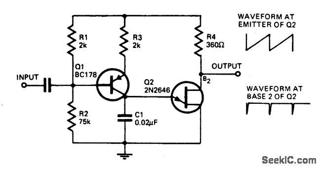
With the component values shown, the oscillator has a frequency of 8 kHz. When an input signal is applied to the base of Q1 the current flowing through Q1 is varied, thus varying the time required to charge C1. Due to the phase inversion in Q1 the direction of output frequency change is 180 degrees out of phase with the input signal. The output may be used to trigger a bistable flip-flop.
Reprinted Url Of This Article:
http://www.seekic.com/circuit_diagram/Signal_Processing/Oscillator_Circuit/SIMPLE_VOLTAGE_CONTROLLED_OSCILLATOR.html
Print this Page | Comments | Reading(3)

Article Categories
power supply circuit
Amplifier Circuit
Basic Circuit
LED and Light Circuit
Sensor Circuit
Signal Processing
Electrical Equipment Circuit
Control Circuit
Remote Control Circuit
A/D-D/A Converter Circuit
Audio Circuit
Measuring and Test Circuit
Communication Circuit
Computer-Related Circuit
555 Circuit
Automotive Circuit
Repairing Circuit
Code: