Signal Processing
Two Wien Bridge low-frequency signal generators for self-made
Published:2011/8/2 1:11:00 Author:Ecco | Keyword: Wien Bridge, low-frequency , signal generator , self-made | From:SeekIC
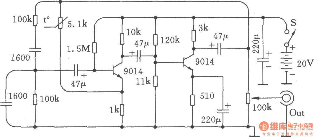
Low frequency signal generator is the common equipment for electronic production debugging, maintenance, here are two circuits, the performance are very good. The two 100kΩ resistors in figure and two 1600pF capacitors determine the oscillation frequency of RC series-parallel selective circuit, it is calculated as f = 1 ÷ (6.28 × R × C). If the unit of R uses kΩ, the unit of C uses μF, the unit of f is kHz, so changing the value of R and C according to the calculation, then you can get a different oscillation frequency. The frequency of RC circuit diagram is l000Hz. It should be noted, the value of resistors and capacitors in two series-parallel network must be the same. This circuit has the advantage of easy startup, good wave and reliable work, it is often called the Wien Bridge oscillator circuit.
Reprinted Url Of This Article:
http://www.seekic.com/circuit_diagram/Signal_Processing/Two_Wien_Bridge_low_frequency_signal_generators_for_self_made.html
Print this Page | Comments | Reading(3)

Article Categories
power supply circuit
Amplifier Circuit
Basic Circuit
LED and Light Circuit
Sensor Circuit
Signal Processing
Electrical Equipment Circuit
Control Circuit
Remote Control Circuit
A/D-D/A Converter Circuit
Audio Circuit
Measuring and Test Circuit
Communication Circuit
Computer-Related Circuit
555 Circuit
Automotive Circuit
Repairing Circuit
Code: