Signal Processing
Voltage Regulator (the 2nd)
Published:2011/7/29 4:27:00 Author:Felicity | Keyword: Voltage Regulator | From:SeekIC
Work of the circuit
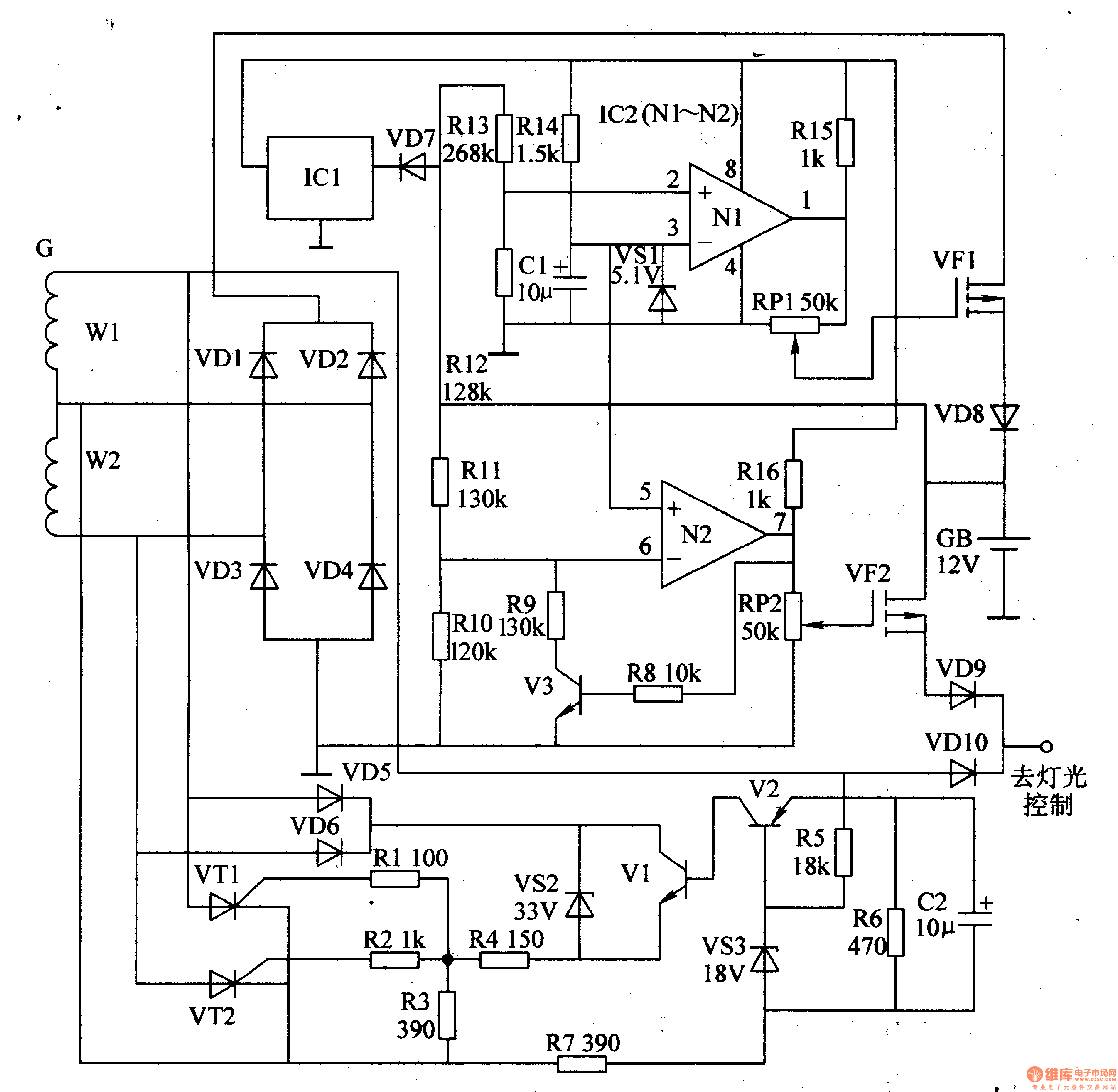
The circuit consists of voluntary stabilizing circuit and battery charging and protecting circuit. (It is showed in picture 7-142.)
Voluntary stabilizing circuitconsists of diodeVD5, VD6,voltage regulatordiodeVS2, VS3,transistorsVl, V2,resistorsRl-R7,capacitorC2 andthyristorVTl, VT2.
Battery charging and protecting circuit consists of capacitor Cl,diodeVDl-VD4, VD7-VDlO,resistorsR8-RlO,potentiometerRPI, RP2,voltage regulatordiodeVSl,transistorsV3,operational amplifierIC2 (Nl, N2,three-terminalvoltage regulatorintegrated circuitICland field-effecttransistorVF1, VF2.
When the speed of the motor is 300Or/min and the AC voltage over W2 is not less than 15V, VT1 and VT2 is transmitted. When thespeed of the motor is low, Vm is cut-off. At the same time, VT1 is transmitted or cut-off. This can stabilize the exporting voltage and make sure the light is bright enough.
When the exporting voltage is over 15V, VF1 is cut-off. In this way, the battery is not over-charged. When the exporting voltage is less than 10.5 V, VF2 is cut-off. In this way, the battery is not over-discharged. Change the value of RP1 and RP2 to change the sensitivity of VF1 and VF2.
Reprinted Url Of This Article:
http://www.seekic.com/circuit_diagram/Signal_Processing/Voltage_Regulator_the_2nd.html
Print this Page | Comments | Reading(3)

Article Categories
power supply circuit
Amplifier Circuit
Basic Circuit
LED and Light Circuit
Sensor Circuit
Signal Processing
Electrical Equipment Circuit
Control Circuit
Remote Control Circuit
A/D-D/A Converter Circuit
Audio Circuit
Measuring and Test Circuit
Communication Circuit
Computer-Related Circuit
555 Circuit
Automotive Circuit
Repairing Circuit
Code: