
Index 6
Smoke Alarm Circuit(Photo-interrupter module)
Published:2013/9/24 20:31:00 Author:lynne | Keyword: Smoke Alarm Circuit(Photo-interrupter module)
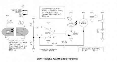
The photo-interrupter is simply an optical coupler with the elements separated with a slot. Anything that enters this slot reduces the current transfer ratio (output current /input current). I used the H21B1 Darlington device since I did not have the H21A1 on hand. I am glad I did, because I learned that it is a better device, requiring far less LED current. Since the H21A1 /H21B1 series is no longer available from DigiKey, I selected a currently available, more inexpensive device—the Sharp GP series—see schematic(s) for details. Sharp appears to be the leader in this product.I did not test the circuit with these devices. (View)
View full Circuit Diagram | Comments | Reading(2774)
Whistle Light Switch
Published:2013/9/23 20:18:00 Author:lynne | Keyword: Whistle Light Switch
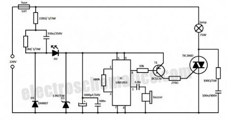
With this whistle light switch you can turn on and off the lighting installation. The main part of this circuit is the UM3763 IC, produced by UMC. The piezo-ceramic buzzer is used here as a microphone and when it receives a tone frequency between 1.2 kHz and 1.8 kHz, the IC’s output will go HIGH. This means that the light will go ON if it was OFF, or go OFF it was ON.
For light control the UM3763 triggers a triac through T1. The supply voltage is taken directly from the main power supply. D1 and D2 diodes are used as rectifiers, and D3 limits the voltage at 3.9 V. D2 LED is used as an indicator of operating or idle state.
Because the whistle light switch circuit is powered from 220V you need to make good isolation and take good precautions. (View)
View full Circuit Diagram | Comments | Reading(1387)
Power Indicator for the Water Softener
Published:2013/9/23 20:15:00 Author:lynne | Keyword: Power Indicator for the Water Softener
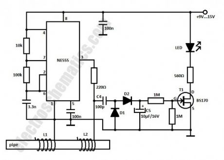
This power indicator circuit is intended to be used as an extension for the water softener. It might be easier to just place a LED but it is better to make a rectifier that detects the presence of the 15 kHz signal generated by the 555 IC.
The rectifier is connected at the water softener system with C4 capacitor. D1 and D2 diodes are used to obtain a DC voltage that is filtered by C5 capacitor. This voltage turns ON the FET that lights up the LED. When there is no signal from the oscillator the LED will not glow. D1 and D2 = 1N4148. (View)
View full Circuit Diagram | Comments | Reading(1906)
Reed Switch as a Current Monitor
Published:2013/9/22 19:59:00 Author:lynne | Keyword: Reed Switch as a Current Monitor
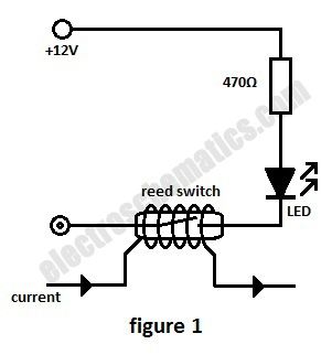

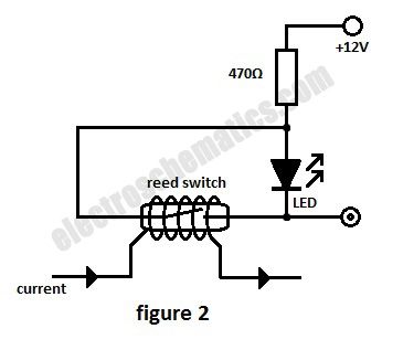
In this current monitoring circuit we use a Reed switch with a LED and a resistor to indicate if is current through a circuit. A Reed switch usually requires between 10 and 100 AT (Ampere-turns = corresponding to the current in a coil multiplied by the number of turns). The lower the AT, the more sensitive the reed switch.
For example a car headlight (both light bulbs) has a current consumption of 7 A or 8 A at 12V so a 50 AT Reed switch requires 7 or 8 turns in order to monitor the current.As soon as one bulb is malfunctioning the current is dropping below half and the switch opens its contact.
(View)
View full Circuit Diagram | Comments | Reading(8178)
DC Motor Speed Controller Project
Published:2013/9/16 22:18:00 Author:lynne | Keyword: DC Motor Speed Controller Project
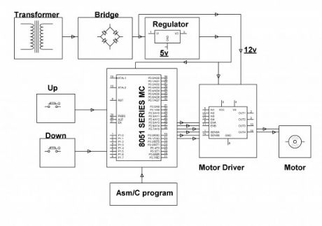
The DC motor speed control project is intended to manage the pace of a DC motor by means of an 8051 sequence micro-controller. The pace of DC motor is straightforwardly relative to the voltage functional across its terminals. Therefore, if voltage through motor terminal is different, then pace can too be different.
This assignment makes use of the above theory to manage the pace of the motor by changing the function series of the throb functional to it (commonly acknowledged as PWM control). The assignment bring into play two input keys interfaced to the micro-controller, which are brought into play to manage the pace of motor. Pulse Width Modulation (PWM) is produced at the yield by the micro-controller as per the series.
The schedule can be printed in Embedded C or Assembly language. The standard voltage supplied or the standard current passing all the way through the motor will alter depending on the function series (ON & OFF moment of the pulse), so the pace of the motor will vary. For receiving PWM indications, motor driver’s IC is connected to the micro-controller for distributing much wanted output for pace control of a small DC machine. In addition the DC motor speed control project can be improved by bringing into play power electrical gadgets like IGBTs to get speed control top capacity industrialized motors.
(View)
View full Circuit Diagram | Comments | Reading(1514)
IR Remote Thyristor Power Controller
Published:2013/9/12 20:28:00 Author:lynne | Keyword: IR Remote Thyristor Power Controller

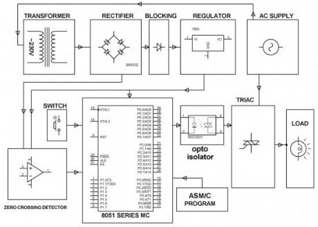
This thyristor power control project is intended to manage the pace of an induction machine for example- fans, by bringing into play a ordinary Television remote. In domestic automatic appliances, ease of using the gadget remotely & controlling the pace of the fan is attained.
An ordinary television remote launches coded infrared statistics to the control panel, which is then acknowledged by an IR antenna or sensor (at the recipient end) interfaced to a micro-controller which is of 8051 family. Each time the button of the TV remote is pressed it launches a particular coded statistics in infrared range. This coded statistics launched by the remote is carried out by the micro-controller to deliver postponed sacking pulses to the thyristor via optical separation. (View)
View full Circuit Diagram | Comments | Reading(1511)
Shadow Sensor Alarm
Published:2013/9/12 20:27:00 Author:lynne | Keyword: Shadow Sensor Alarm

Shadow sensors are widely used to detect the movement of a person in a confined area. Many circuits published earlier have a serious drawback that only one light dependent resistor (LDR) is used for shadow detection.Needless to say, this is not a perfect solution!
Described here is a simple but improved circuit of a smart shadow sensor alarm, which can register a shadow when there is a light difference. Here two 5mm LDRs are used with the popular Op-amp LM741CN to drive an active piezo-sounder when a “valid” shadow is detected. The whole shadow sensor circuit can be powered from four 1.5V AA cells (6VDC), or similar dc supply sources. (View)
View full Circuit Diagram | Comments | Reading(1639)
Non-Contact Human Interface Capacitive Switch
Published:2013/9/12 20:25:00 Author:lynne | Keyword: Non-Contact Human Interface Capacitive Switch

Simple, highly sensitive capacitive ON/OFF switch pads change the state of a latch and turn on an LED without requiring actual physical human contact. The pad may be insulated. A range of 12mm is easily obtained and sensitivity is adjustable.Power is supplied via a common 9V battery.
Central is the 74HC02 CMOS NOR Gate IC. The gate input capacitance is typically only 3pF. To enable a sufficient voltage to change states reliably a 100M bias resistor is recommended. I had to check to see if such a resistor is easily available — yes, it is available from DigiKey at a cost is only $0.52. Or you can fabricate a resistor via series 10 or 22M resistors — that is what I did to obtain 50M. The ‘low sides’ of these resistors are tied to a bias potentiometer so that the static gate input voltage may be set very close to the threshold. Sensitivity is also increased by reducing Vcc to 2.7V (minimum specified operating voltage is 2.0V). I was able to obtain a range of about 16mm using a 50M resistor and paperclip ‘non-contact pad.’
I also experimented with the CD4011 NOR gate—it worked reasonably well, but it has higher gate input capacitance (5pF) and minimum operating voltage is also higher at 3.0V.
A 2N7000 N-Channel MOSFET (Q1) drives a 20mA ultrabright white LED. Note that the gate output voltage may be insufficient to fully turn on the transistor because the maximum Vgs threshold voltage is 3V. Fortunately, most run close to the typical 2.1V. In case one does not work, try another device.
Quiescent battery drain is only 56uA.
The 1M input resistors protect the IC against static discharge and actually allow touching of the pad without danger.
(View)
View full Circuit Diagram | Comments | Reading(1473)
Three Phase Solid State Relay
Published:2013/9/11 20:46:00 Author:lynne | Keyword: Three Phase Solid State Relay
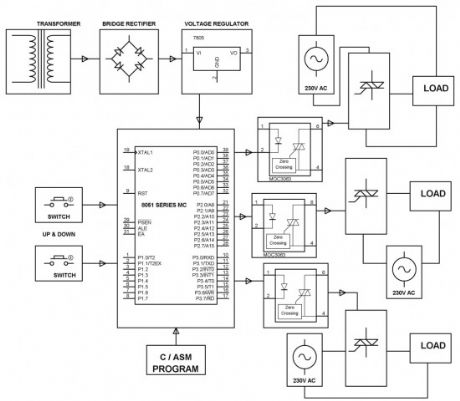
This three phase solid state relay project kit is intended for a system of three phase solid state relay. It integrates three solo phase units where each & every phase is managed independently with the help of a power triac with RC snubber set-up for zero voltage controlling. Opto-isolators are brought into play for each & every phase to obtain controlling signals from a micro-controller which is of 8051 family.
Loads are coupled in sequence with a cluster of triacs being impelled by the opto-isolator. The micro-controller which is from 8051 family is intended to produce output pulses following zero voltage pulse to make sure that the load is getting turned ON at zero cross of the delivered waveform. The zero crossing characteristic of the TRIAC impeller, (an opto-isolator) make certain low sound production, as a result evading unexpected in-rush of current on defying and inductive loads. (View)
View full Circuit Diagram | Comments | Reading(1316)
Strobe Lights Project
Published:2013/9/10 19:52:00 Author:lynne | Keyword: Strobe Lights Project
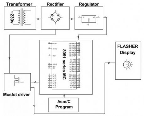
Stroboscopic effects of lights for nightclubs are realized by bringing into play old white Light Emitting Diodes (LEDs) swapping the ejection lanterns/lamps for superior effectiveness at minimal cost. This control is achievable by instantaneously changing the Light Emitting Diodes on & off at elevated volts for small amount of time span. This speedy control of power from complete shine to complete off aids in creating a stroboscopic outcome which is commonly bring into play in discotheque dance floorboards for improved effects.
8051 family’s programmable micro-controller is fit into placed to give such effect being motivated by a MOSFET for group of Light Emitting Diodes. The microcontroller as per schedule produces ON/OFF commands at lofty rate as a result providing the stroboscopic effect of lights. Since the controller provides merely 5volts drive, it’s not achievable for the MOSFET to be constantly be switched ON at that high voltage. A crossing point transistor is made use of amid the controller productivity and the MOSFET for driving the same. (View)
View full Circuit Diagram | Comments | Reading(1015)
555 Voltage Doubler Relay Driver
Published:2013/9/10 19:49:00 Author:lynne | Keyword: 555 Voltage Doubler Relay Driver

These novel relay driver circuits have the ability to pick up a relay with a coil voltage rating equal to double Vcc. After pickup, the relay armature is held via the application of Vcc. Under this condition, the coil power is reduced by the square of the voltage ratio, or to 25%. This is the ultimate in relay economy—the reduction of wasted coil power. In typical relay economy circuits, the coil power may be reduced to 25%, but the series dropping resistor dissipates an equal amount of power. In the voltage doubler relay driver, THERE IS NO SERIES RESISTOR! I believe that these voltage doubler relay driver circuits are new to the world.
The versatile 555 performs this interface function well. It is configured as a Schmitt trigger inverter /driver with two outputs: Totem pole and open collector. When output (pin 3) goes low, Q1 turns on and sources Vcc to the positive side of the coil. At the same time, the reset line (pin 7) goes low and drives the cathode of C1 to -12V. Thus the difference between the collector of Q1 and the cathode of C1 is 24V momentarily. After C1 is discharged, D2 conducts the coil current to common thus applying 12V minus one diode drop to the relay coil.
When the input to the 555 goes low, pin 3 goes high, pin 7 is turned off and the relay drops. At this time C1 starts to recharge—its charge time constant is 0.47sec so it will be ready to fire again in about 2sec.
The input logic threshold may be adjusted down to TTL levels via connecting the suggested voltage divider (R4 & R5) to pin 5 (see schematic). This is recommended for only the CMOS TLC555 device. Otherwise, the standard bipolar 555 should work fine. (View)
View full Circuit Diagram | Comments | Reading(1132)
ON OFF Touch Switch with 555
Published:2013/9/9 20:27:00 Author:lynne | Keyword: ON OFF Touch Switch with 555
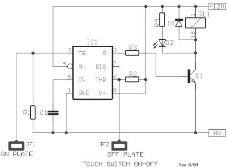
This ON OFF touch switch circuit is based on the well known timer IC 555 (IC1), which drives a relay that acts like a switch. The metal surfaces can have what form we want, but it should be clean and very close to the circuit.Touch plate MP1 in order to close the contact of relay RL1 [ON], or plate MP2 in order to open the contact of RL1 [OFF]. The Led D2 turns on when the contacts of RL1 are closed. Two small pieces of metal can be used as sensor plates.
Components List
R1 = R2 = 3.3MR3 = 10KR4 = 1KC1 = 10nFD1 = 1N4007Q1 = BC547IC = NE55512V relay (View)
View full Circuit Diagram | Comments | Reading(1786)
Zero Voltage Switching (ZVS) for Lamp Life Extender
Published:2013/9/9 20:26:00 Author:lynne | Keyword: Zero Voltage Switching (ZVS) for Lamp Life Extender
This lamp life extender project is intended to create an appliance to enhance the existence of luminescent lanterns or lamps. Luminescent lanterns or lamps show signs of very small resistance in freezing circumstances owing to which it pulls lofty current while turned ON, as a result breakdown is fast.
Frequent switching of lantern or lamps may turn the load at maximum supply voltage. When such random switching takes place while the lantern or lamp is enclosing small resistance (freezing circumstances) then the electric current further go sky-high (at the point of max supply voltage turn ON) resulting in impulsive collapse of the lantern or lamp. The planned project offers an answer by fitting into place a TRIAC in such a manner that the turn ON time is exactly directed by precisely sacking it after noticing the zero cross end of the waveform of delivered voltage. This would outcome in electric current waveform increasing from zero at the moment of switch to peak value, in this manner escalating the lantern or lamp’s life. (View)
View full Circuit Diagram | Comments | Reading(1322)
Touch Sensor Switch Circuit with 555 timer
Published:2013/9/8 20:33:00 Author:lynne | Keyword: Touch Sensor Switch Circuit with 555 timer
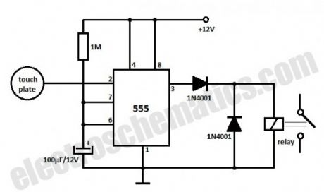
This is a very simple touch sensor switch that is build with the 555 timer IC.You just need to touch the metal plate and the relay gets energised and is kept in this state for about 100 seconds, then is released.
This kind of sensor switch is suitable for making touch operated bells, buzzers of small toys which operate for a small time and then switch off automatically.
The input impedance of the trigger is very high and the touch sensor switch can be triggered by the voltage induced in the human body. The relay is a 12 V DC relay operating at currents less than 200 mA.
(View)
View full Circuit Diagram | Comments | Reading(1997)
Test Human Reaction Time with the 555 IC
Published:2013/9/8 20:32:00 Author:lynne | Keyword: Test Human Reaction Time with the 555 IC
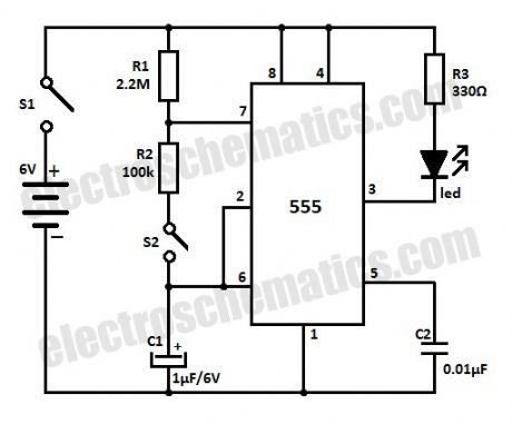
With this simple circuit that is built with the 555 IC you can test human reaction time. You can find out how fast do you react by trying to catch a flashing LED.How does the human reaction tester works?
When S1 is ON the circuit acts as a astable multivibrator and the LED is lit for about 0.1 second and is flashing every 1.5 seconds. Since the human reaction time is more than this (>100 ms) it will be quite difficult to catch the LED when is ON. If you press S2 within that 0.1 second period of time when the LED is ON then the discharging of C1 stops and the LED stays lit.
You can change the ON and OFF alternating periods by changing the values of R1 and R2 or C1 to suit your preferences.
(View)
View full Circuit Diagram | Comments | Reading(1785)
Light Activated Relay with 555 IC
Published:2013/9/4 20:01:00 Author:lynne | Keyword: Light Activated Relay with 555 IC
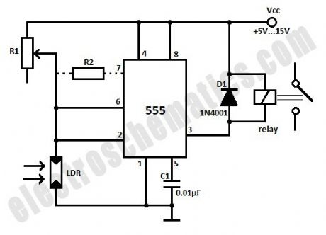
This light activated relay circuit presented here uses the 555 timer IC and a light dependent resistor or LDR to form a light sensitive relay in an intruder alarm system or for switching on a lamp at Sun set and off at Sun rise.
Potentiometer R1 value must be chosen and then adjusted that under normal conditions when the light is falling on the LDR the voltage across the LDR is less than 1/3 of Vcc. The output of the 555 IC is high now. The actual value of R1 will depend on the resistance of the LDR.
When the light fades or is interrupted by an intruder, the voltage across it rises above 2/3 of Vcc, tripping the IC flip-flop. The output goes low activating the relay. When the light is restored, voltage falls below 1/3 of Vcc, again tripping the flip-flop causing the output to go high and the relay drops.
The difference of 1/3 of Vcc between turning on and turning off voltages prevents relay chatter. This differential can be reduced by connecting a resistor R2 shown dotted in the schematic. Its value is about one and a half times of the LDR resistance in its illuminated condition. Use a 6V or 12V relay with a current of 200mA max.
(View)
View full Circuit Diagram | Comments | Reading(1833)
Automatic Bike Headlight Switch
Published:2013/9/4 19:59:00 Author:lynne | Keyword: Automatic Bike Headlight Switch
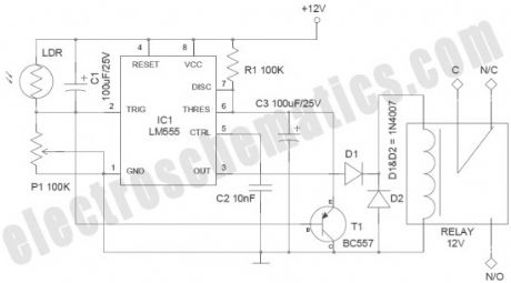
Improved bike headlight switch circuit presented here has been designed to switch bike headlight on (or similar loads) at a presettable ambient light level. The circuit is based on the renowned timer chip LM555 (IC1), here triggered by a decrement in ambient light level. Here is a 220V automatic light switch, just in case you need one.
Bike Headlight Switch Notes
The whole circuit should be powered from the 12V bike battery
Slight intervention in the existing electrical wiring of the vehicle may become necessary to add this circuit
Use of a medium-size encased LDR is recommended for reliable operation. Fit the LDR at the front side of the bike in an appropriate position
The relay used in the prototype draws near 37.5 mA. 555 IC output can switch up to 100mA, which is adequate for driving the relay
555 IC will only rise to near 10v for the 12V input supply and the diode D1 will drop 0.7Volt. As a result the 12V relay will only get about 9.3Volt. However, pick-up voltage of a standard 12V relay is 9V, this is not a problem. D1 is added intentionally to avoid episodic timer latch up (View)
View full Circuit Diagram | Comments | Reading(1250)
Microcontroller Relay Interface and Driver
Published:2013/9/3 20:14:00 Author:lynne | Keyword: Microcontroller Relay Interface and Driver
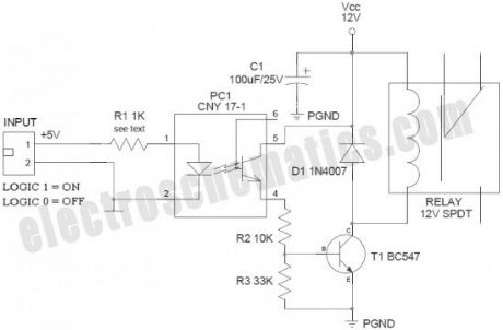
Many microcontroller designs typically mix multiple interfacing methods. A microcontroller (µC) system can be viewed as a system that reads from inputs, performs processing and writes to outputs. Microcontrollers are useful to the extent that they communicate with other devices, such as sensors, motors, switches, keypads, displays, memory and even other micro-controllers. Often a need arise to interface output of the microcontroller with an electromagnetic relay (EMR).
Relays are devices which allow low power circuits to switch a relatively high Current and/or Voltage on/off. Here is a simple microcontroller-relay interface circuit with perfect “galvanic isolation”. “Galvanic isolation”means an isolation between two circuits, i.e. no metal conduction between those circuits. Transfer will then take place for instance optical or by induction. Galvanic means “related to DC”. Galvanic Isolation says that the driver circuit is separated from the signal source in such a way that DC current cannot bridge the connection. The widely accepted method for galvanic isolation is the use of optical isolator (optocoupler/photocoupler).
(View)
View full Circuit Diagram | Comments | Reading(1388)
White LED Night Light Circuit
Published:2013/9/3 20:02:00 Author:lynne | Keyword: White LED Night Light Circuit

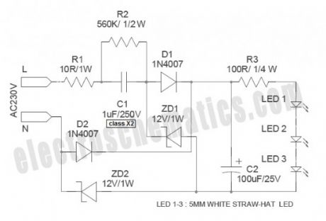
White Light Emitting Diodes recently available can be used as a powerful alternative to incandescent lamps in lighting applications. Today’s White LEDs are less expensive, draw much less current, and project a fairly well focused beam.
Described here is a simple circuit of an efficient White LED Night Light which can be directly powered from AC230V supply. First of all, note that a “capacitive transformerless power supply” is used in this circuit.
When a capacitor and resistor are connected in series to an AC source, as shown here, a constant current can be maintained through the resistor, so long as the reactance of the capacitors is much greater than the resistance. The current flow is dependent upon the value of the capacitor and assuming that V1 is much greater than V2, the value of the current can be assumed to be: IRMS = V1/XC where XC is the reactance of the capacitor. According to this, if we are using a 1uF capacitor , the current value is near 70mA at 230VAC/50Hz input. In order to get a DC voltage using this method, as usual, rectifiers and filter capacitors should be added.
(View)
View full Circuit Diagram | Comments | Reading(1244)
Run/Stop Relay
Published:2013/9/1 20:47:00 Author:lynne | Keyword: Run/Stop Relay
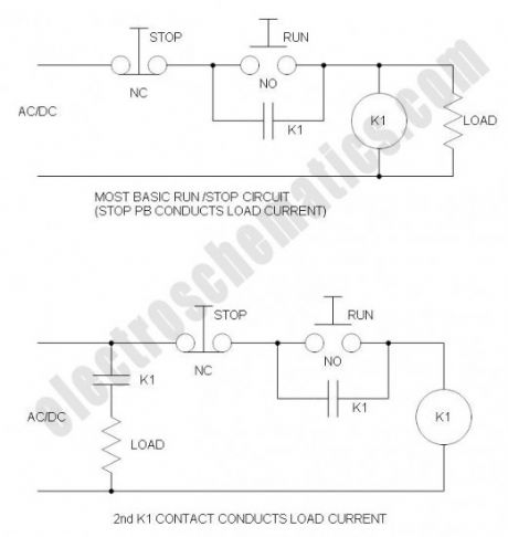
Safety is a major concern in a good many motor-driven applications. This is true in industrial applications where motion starts when power is applied and especially true when power is restored after an outage. In such cases, unwanted or unexpected motion is a risk to life or limb. The most simple solution to this problem is the simple, time-proven Run /Stop Relay Circuit.
With this control circuit, motion cannot commence (or restart) without the operator’s specific pushbutton command. While simple, there are numerous variations and enhancements as you will see, and the benefits are clearly obvious. (View)
View full Circuit Diagram | Comments | Reading(1268)
| Pages:6/312 1234567891011121314151617181920Under 20 |
Circuit Categories
power supply circuit
Amplifier Circuit
Basic Circuit
LED and Light Circuit
Sensor Circuit
Signal Processing
Electrical Equipment Circuit
Control Circuit
Remote Control Circuit
A/D-D/A Converter Circuit
Audio Circuit
Measuring and Test Circuit
Communication Circuit
Computer-Related Circuit
555 Circuit
Automotive Circuit
Repairing Circuit