
LED and Light Circuit
Index 61
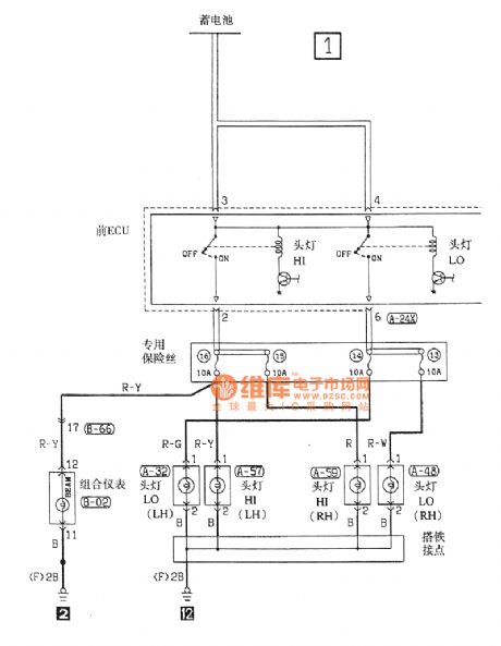
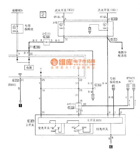
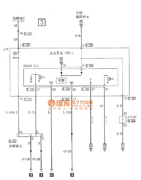
Southeast Ling Sheng head lamp electric system circuit
Published:2011/7/20 21:04:00 Author:leo | Keyword: Head lamp, electric system
View full Circuit Diagram | Comments | Reading(680)
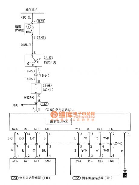
Southeast Ling Sheng car reverse radar electric system circuit
Published:2011/7/20 21:08:00 Author:leo | Keyword: Car reverse radar, electric system
View full Circuit Diagram | Comments | Reading(716)
MAX684 charge-pump drive white light LED circuit
Published:2011/7/13 21:02:00 Author:leo | Keyword: Charge-pump, white light LED
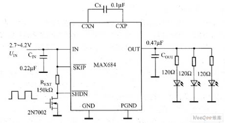
MAX684 charge-pump drive white light LED circuit is like what the picture shows. Its work voltage is from 2.7 V to 4.21 V and can output 5 V voltage and 50mA current. It does not need shielded inductor and just need a resistance and three capacitors. If the practical need is more than three white light LEDs, it can take MAX683 and MAX682 which can offer separately 100mA and 250 mA output current. Especially, the MAX683 can drive more than 16 white light LED which are par ally connected. (View)
View full Circuit Diagram | Comments | Reading(694)
Sequenced flashing AC flash
Published:2011/7/16 3:10:00 Author:leo | Keyword: Sequenced flashing, AC flash

This circuit uses a simple circular counter. The control ports of triac form a part of load. And the three incandescent lamps brighten up in turn and usually one lamp lightens at one time. Impulse frequency can be adjusted which can control the change of lamps. Time period for the change of lamps can be set from 0.1 second to 8 seconds. If the circuit in the dashed box is added, the lamp lightened before will keep light when the next lamp lightens. (View)
View full Circuit Diagram | Comments | Reading(736)
Sequenced switching over load circuit
Published:2011/7/16 3:19:00 Author:leo | Keyword: Sequenced switching, load
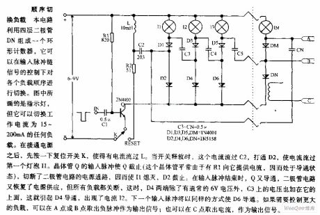
This circuit uses four diodes DN to form a circular counter. It can switch over the sequence of the loads under the control of input impulse signals. As the picture shows, except the indicator lamp, it can switch over any load with the current of 15 mA to 200 mA. When connecting the power resources, please click reset switch K to offer current to Lo. When K is cut off, the current passes through C2. After that, please open up D2, there will be current passing through I1. (View)
View full Circuit Diagram | Comments | Reading(672)
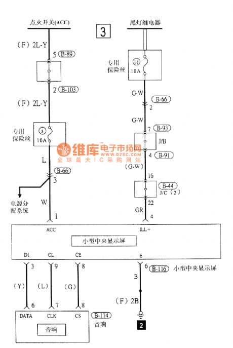
Southeast Ling Sheng audio(small central screen) electric system circuit
Published:2011/7/20 21:30:00 Author:leo | Keyword: Audio(small central screen), electric system
View full Circuit Diagram | Comments | Reading(568)
Light circuit in case of power failure
Published:2011/7/16 2:57:00 Author:leo | Keyword: Light ciricuit, power failure
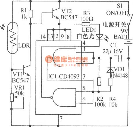
It is not safe for children to walk around in the study when the power is cut suddenly. As the picture shows, it is a light circuit made by LED. This lamp uses battery to supply power and has a low power consumption. If it is set beside the desk, when the power is cut suddenly, it will offer enough light for children’s walking out the room. In order to save the power, LED uses adaptive lighting. IC1 selects CMOS integrated circuit CD4093 and VT1 and VT2 select triode BC547.Other components are shown in the picture. (View)
View full Circuit Diagram | Comments | Reading(992)
CAT3200/CAT3200-5 Charge-pump Driving White LED Circuit
Published:2011/7/13 7:34:00 Author:Michel | Keyword: Charge-pump, Driving, White LED Circuit
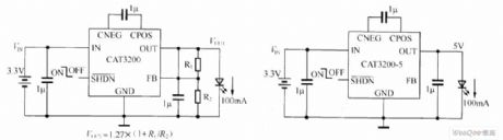
CAT3200 and CAT3200-5 are switch capacitor boost converter and it can output adjustable voltage with low noise.CAT3200-5's output voltage is fixed on 5 V, CAT3200 uses external resistance and the output voltage can be adjusted.Charge-pump with fixed frequency,2MHz is allowed to use small ceramic capacitors and a wider power supply input voltage range (2.7 ~ 4.5 V) can support up to 100 mA maximum output current.Shut-off control input function allows devices to enter closed mode, which makes the source current reduce to less than 1μA.In short-circuit or overload condition, the device gets turn-back current limit protection and overheating protection.In addition, soft start and the conversion rate control surge current when power is on. (View)
View full Circuit Diagram | Comments | Reading(855)
AAT3110 Charge-pump Driving White LED Circuit
Published:2011/7/13 7:40:00 Author:Michel | Keyword: Charge-pump Driving, White LED Circuit
Capacitance type charge-pump is divided into frequency doubling and fractional frequency according to its boost way.The efficiency of the frequency doubling charge-pump is about 90% and the efficiency of fractional frequency charge-pump is 93%~95%.Capacitive charge-pump is divided into constant voltage output and constant current output according to the output.According to the driving LED way,it is divided into LED parallel constant voltage drive, single constant current driver, series constant current driver etc.Inductive booster device is constant current output, the output voltage is higher and it drives LED in series way.The charge-pump composed of AAT3310 is shown as the picture 1.This charge-pump uses output voltage power supply circuit in parallel manner with the features of few external circuit devices,simple walk line and high conversion efficiency. (View)
View full Circuit Diagram | Comments | Reading(722)
Basic Circuit of Switch Power Drive LED Array
Published:2011/7/11 23:37:00 Author:Michel | Keyword: LED Array, Basic Circuit
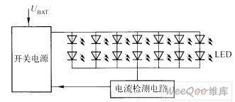
Usually the driver provides over 25W power when automobiles' front lights use white LED blacklight.Because one advantage of white LED components is high efficiency and drive electronic components should also improve efficiency, so as to play the advantages of white LED technology fully.The switch power drive white LED array circuit is showed as above.
Picture:Basic Circuit of Switch Power Drive LED
(View)
View full Circuit Diagram | Comments | Reading(674)
R1212 Driving White LED Application Circuit
Published:2011/7/11 23:48:00 Author:Michel | Keyword: White LED, Application Circuit
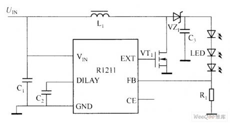
Ricoh R1211 uses CM0S low power consumption and current control switch type boost converter. Its periphery circuit is simple and there is just an inductor, a diode, a mosfet,some resistance and capacitance.The input voltage range is 2.5 ~ 5.5 V and it is suitable for single quarter lithium ion battery or ordinary dry battery power supply. The chip inside uses PWM,which can produce as much as 15 V output voltage and it drives three series white LED.
R1211 series chip adopts the phase compensation feedback loop,which makes whole boost conversion process response more rapidly and output voltage becomes more stable. (View)
View full Circuit Diagram | Comments | Reading(622)
Delay lamp circuit using relay (6)
Published:2011/7/20 2:59:00 Author:zj | Keyword: Delay lamp circuit, using relay
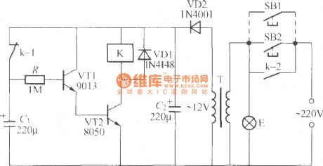
As shown in the figure, delay duration depends mainly on the R and C1 discharge time constant. The magnification of transistor VT1 and VT2affects delay time. The beta is big, the delay time is relatively long. When VT1, VT2 beta ≥100, using data as shown in the figure, the lamp E can be lighted for about 10min each time pressing the switch. (View)
View full Circuit Diagram | Comments | Reading(747)
Delay lamp circuit using relay (4)
Published:2011/7/20 3:01:00 Author:zj | Keyword: Delay lamp circuit, using relay
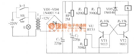
In the graph, K can adopt JZC-22F, DC12V miniature electromagnetic relay. The coil resistance is 400, and contact capacity is 5A. VT1, VT2 require using type 9013 transistor whose performance should be as consistent as possible. Beta value is about 100. Note: VT1 beta value cannot be greater than VT2, otherwise the circuit can not work normally. (View)
View full Circuit Diagram | Comments | Reading(1168)
Touch type delay lamp circuit using music IC(CIC8251)
Published:2011/7/20 3:03:00 Author:zj | Keyword: Touch type, delay lamp circuit
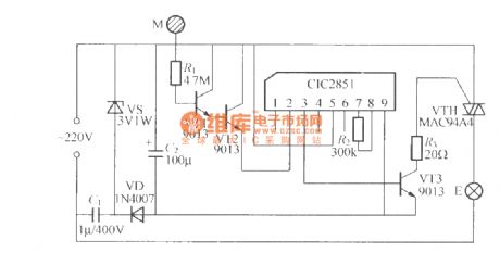
As the diagram shows it is a touch type delay lamp circuit using music IC(CIC8251). It makes use of a music integrated circuit memory function to realize the control delay. The delay time is 1min. The circuit can use common KD-9300serie music IC. But generally this serie music IC are without external oscillation resistance. The circuit delay time is about 20s fixed by chip circuit. (View)
View full Circuit Diagram | Comments | Reading(1243)
Light control street lamp circuit using MAX837
Published:2011/7/20 3:02:00 Author:zj | Keyword: Light control, street lamp circuit
View full Circuit Diagram | Comments | Reading(741)
Battery-powered fluorescent lamp circuit (2)
Published:2011/7/20 20:12:00 Author:Ecco | Keyword: Battery-powered, fluorescent lamp
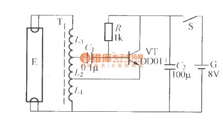
The circuit shown as the chart uses a battery with 8V battery to light 6 ~ 8W fluorescent tube, which can be used in emergency lighting as sudden power outage or flowing palces outdoors . T needs to be made by yourself: it uses E5 ferrite core with Φ0.53 high-intensity polyester, and L1 has 22 turns and L2 has 17 turns around, and L3 switch to uses Φ0.21mm high-intensity polyester enameled wire with 225 turns around, and the head and tail are connected.
(View)
View full Circuit Diagram | Comments | Reading(3002)
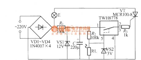
Auto-dimming lamp circuit diagram
Published:2011/7/20 20:13:00 Author:Ecco | Keyword: Auto-dimming, lamp
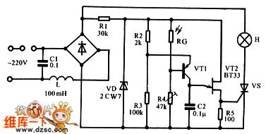
The circuit is shown as the chart. AC voltage is rectified by the bridge pile, of which one way is stabilized by stabilovolt tube VD through R1 to provide 9V pulse DC voltage for control circuit; another way is added to the light H and SCR VS. Change the conduction angle of VS can change the brightness of light H; the currrent through H is the pulsating DC current. The control circuit uses the pulsating DC current to ensure the output trigger pulse and anode voltage of SCR VS be synchronization.
(View)
View full Circuit Diagram | Comments | Reading(987)
LED extinguishment circuit
Published:2011/5/13 3:42:00 Author:Nicole | Keyword: LED
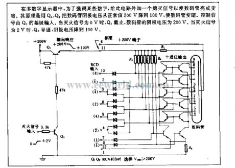
In multi-digital display, in order to stress some numbers, so a black out signal is added to this circuit, then the LED will brighten or darken. The principle: LED cathode voltage is dropped from 200V to 100V by Q1, Q2, LED will draken. Control singal is outputed by Q2 base. When the fire extinguishment singal is 0V, Q2 cuts off, LED cathode voltage is 200V. When the fire extinguishment singal is 2V, Q2 turns on, cathode voltage drops to 100V. (View)
View full Circuit Diagram | Comments | Reading(579)
Delay singal light battery life circuit
Published:2011/5/13 2:49:00 Author:Nicole | Keyword: singal light, battery life
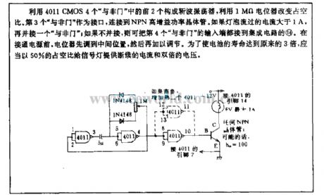
Chopped wave oscillator is composed of the first two 4011 CMOS four NAND gate , the duty ratio is changed by 1MΩ potentiometer. As interface, the third NAND gate is connected to NPN high gain power transistor. If the bulb's current is higher than 1A, then paralleling a NAND gate ; if it does not parallel, you can connect the input terminal of the fourth NAND gate to IC's (14). Before power supply is turned on, potentiometer is adjusted to the middle position, then it can be regulated. In order to make the battery life 3 times longer than before, it should provide singal light discontinuous current and double voltage with 50% duty ratio. (View)
View full Circuit Diagram | Comments | Reading(644)
Xenon flashtube marker circuit
Published:2011/5/13 2:46:00 Author:Nicole | Keyword: xenon flashtube, marker
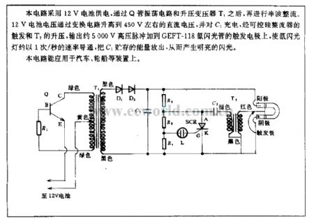
This circuit adopts 12V battery power supply, after Q tube oscillation circuit and step-up transformer T1, then it is half wave rectified. 12V battery voltage will rise to 450V DC voltage by converting circuit, charging to C1, it outputs about 5000V high voltage pulse to add to the trigger electrode of GEET-118 xenon flashtube by the trigger of SCR rectifier and the boost of T2, then the xenon flashtube will turn on with 1/s, discharging the energy stored in C1, to produce bright flashing. (View)
View full Circuit Diagram | Comments | Reading(2461)
| Pages:61/72 At 20616263646566676869707172 |
Circuit Categories
power supply circuit
Amplifier Circuit
Basic Circuit
LED and Light Circuit
Sensor Circuit
Signal Processing
Electrical Equipment Circuit
Control Circuit
Remote Control Circuit
A/D-D/A Converter Circuit
Audio Circuit
Measuring and Test Circuit
Communication Circuit
Computer-Related Circuit
555 Circuit
Automotive Circuit
Repairing Circuit