Filter Circuit
2_20_kHz_SELF_TUNING_BANDPASS
Published:2009/7/2 8:13:00 Author:May | From:SeekIC
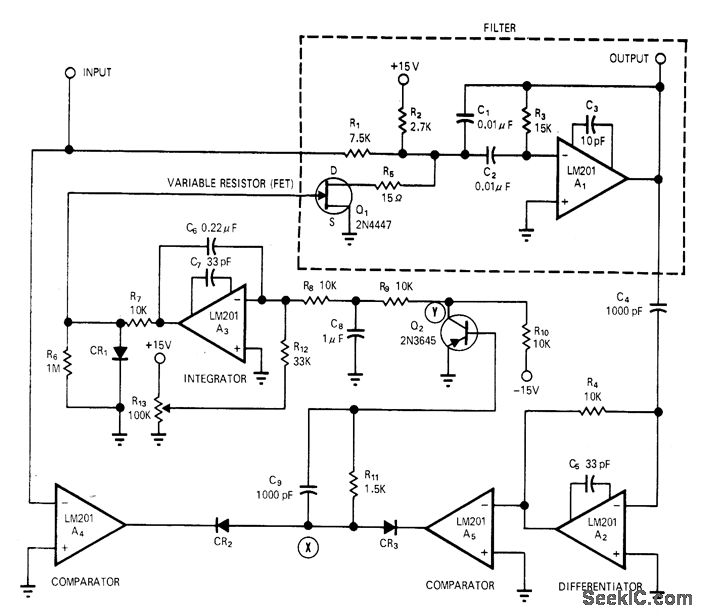
Center frequency of filter is automatically adjusted to track signal frequency, for optimum noise rejection when input frequency varies over wide range as it does with many types of vibrating transducers.Requires no reference frequency and no intemal oscillator or synchronizing circuits. Flequency range can be extended in decade steps by capacitor switching. When filter is not tuned to input frequency, phase shift is not 180° and phase detector applies error signal to gate of FET to control its drain-source resistance. Phase detector A4-A5-CR2-CR3 and FET form part of negative-feedback loop around filter, so error in phase changes resistance of FET and thereby retunes filter, Article gives design equations, operational details, and waveforms at various points in circuit.-G. J. Deboo and R.C. Hedlund, Automatically Tuned Filter Uses IC Operational Amplifiers, EDN/EEE Magazine, Feb.1, 1972, p 38-41.
Reprinted Url Of This Article:
http://www.seekic.com/circuit_diagram/Basic_Circuit/Filter_Circuit/2_20_kHz_SELF_TUNING_BANDPASS.html
Print this Page | Comments | Reading(3)

Article Categories
power supply circuit
Amplifier Circuit
Basic Circuit
LED and Light Circuit
Sensor Circuit
Signal Processing
Electrical Equipment Circuit
Control Circuit
Remote Control Circuit
A/D-D/A Converter Circuit
Audio Circuit
Measuring and Test Circuit
Communication Circuit
Computer-Related Circuit
555 Circuit
Automotive Circuit
Repairing Circuit
Code: