AIC1571

Features: Provides 3 Regulated Voltages for Microprocessor Core, Clock and GTL Power. Simple Voltage-Mode PWM Control. Dual N-Channel MOSFET Synchronous Driver. Operates from +3.3V, +5V and +12V Inputs. Fast Transient Response. Full 0% to 100% Duty Ratios. ±1.0% Output Voltage for VCORE and ±2.0%...

product image

AIC1571 Picture
SeekIC No. : 004279023 Detail

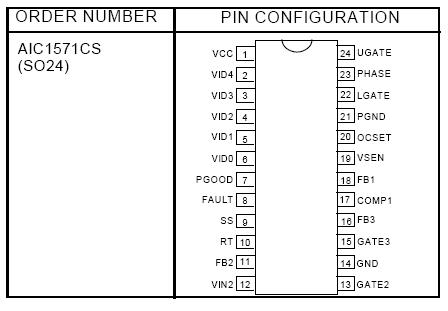
AIC1571: Features: Provides 3 Regulated Voltages for Microprocessor Core, Clock and GTL Power. Simple Voltage-Mode PWM Control. Dual N-Channel MOSFET Synchronous Driver. Operates from +3.3V, +5V and +12V In...

floor Price/Ceiling Price

Part Number:
AIC1571
Supply Ability:
5000

Price Break

  • Qty
  • 1~5000
  • Unit Price
  • Negotiable
  • Processing time
  • 15 Days
Total Cost: $ 0.00

SeekIC Buyer Protection PLUS - newly updated for 2013!

  • Escrow Protection.
  • Guaranteed refunds.
  • Secure payments.
  • Learn more >>

Month Sales

268 Transactions

Rating

evaluate  (4.8 stars)

Upload time: 2024/5/1

Payment Methods

All payment methods are secure and covered by SeekIC Buyer Protection PLUS.

Notice: When you place an order, your payment is made to SeekIC and not to your seller. SeekIC only pays the seller after confirming you have received your order. We will also never share your payment details with your seller.
Product Details

Description


Features:

Provides 3 Regulated Voltages for Microprocessor Core, Clock and GTL Power.
Simple Voltage-Mode PWM Control.
Dual N-Channel MOSFET Synchronous Driver.
Operates from +3.3V, +5V and +12V Inputs.
Fast Transient Response.
Full 0% to 100% Duty Ratios.
±1.0% Output Voltage for VCORE and ±2.0% Output Voltage Reference for VCLK and VGTL.
TTL Compatible 5-bit Digital-to-Analog Core Output Voltage Selection. Range from 1.3V to 3.5V.
0.1V Steps from 2.1V to 3.5V.
0.05V Steps from 1.3V to 2.05V.
Adjustable Current Limit without External Sense Resistor.
Microprocessor Core Voltage Protection against Shorted MOSFET.
Power Good Output Voltage Monitor.
Over-Voltage and Over-Current Fault Monitors.
200KHz Free-Running Oscillator Programmable up to 350KHz.


Application

Full Motherboard Power Regulation for Computers.
Power Integrations for 3 Output Power System.


Pinout

  Connection Diagram


Specifications

Supply Voltage, VCC.....................................................................................+15V
PGOOD, FAULT and GATE Voltage.................................. GND -0.3V to VCC +0.3V
Input, Output , or I/O Voltage .....................................................GND -0.3V to 7V
Recommended Operating Conditions
Supply Voltage; VCC................................................... +12V±10%
Ambient temperature Range.........................................0°C~70°C
Junction Temperature Range ......................................0°C~100°C
Thermal Information
Thermal Resistance, JA
SOIC package ..................................................................100°C/W
SOIC package (with 3in2 of copper)................................. 90°C/W
Maximum Junction Temperature (Plastic Package)...................................... 150°C
Maximum Storage Temperature Range...........................................-65°C ~ 150°C
Maximum Lead Temperature (Soldering 10 sec)............................................300°C


Description

The AIC1571 combines a synchronous voltage mode controller with two linear controllers as well as the monitoring and protection functions in this chip. The PWM controller regulates the microproc-essor core voltage with a synchronous rectified buck converter. One linear controller regulates power for the GTL bus and the other linear control-ler provides power for the clock driver circuit or memory (1.8V)


An integrated 5 bit D/A converter that adjusts the core PWM output voltage from 2.1V to 3.5V in 0.1V increments and from 1.3V to 2.05V in 0.05V increments. The linear regulator uses an internal driver AIC1571 to provide 2.5V2.5%. The linear controller drives with an external N-channel MOSEFET to provide 1.5V2.5%.

AIC1571 monitors all the output voltages. Power Good signal is issued when the core voltage is within 10% of the DAC setting and the other lev-els are above their under-voltage levels. Over-voltage protection for the core output uses the lower N-channel MOSFET to prevent output volt-age above 115% of the DAC setting.
The PWM over-current function monitors the out-put current by using the voltage drop across the upper MOSFETs RDS(ON), eliminating the need for a current sensing resistor.


Customers Who Bought This Item Also Bought

Margin,quality,low-cost products with low minimum orders. Secure your online payments with SeekIC Buyer Protection.
Power Supplies - External/Internal (Off-Board)
Computers, Office - Components, Accessories
Cables, Wires
Motors, Solenoids, Driver Boards/Modules
Connectors, Interconnects
View more