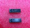
DescriptionThe LM1889 is designed to interface audio, color difference,and luminance signals to the antenna terminals of a 7V receiver.It consists of a sound subcarrier oscillator, chroma subcarrier oscillator, quadrature chroma modulators, and RF oscillators and modulators for two low-VHF channels.The LM1889 allows video information from VTR's, games,test equipment, or similar sources to be displayed on black and white or color TV receivers.When used with the MM57100 and MM53104, a complete TV game is formed.The LM1889 is designed to operate over a wide range of supply voltages so that much of the time it can utilize the signal source power supplies.
Features of the LM1889 are:(1)do channel switching; (2)12V to 18V supply operation; (3)excellent oscillator stability; (4)Low intermodulation products; (5)5 Vp-p chroma reference signal; (6)may be used to encode composite video.To preserve the do content of the video signal, amplitude modulation of the RF carrier is done in one direction only,with increasing video (toward peak white) decreasing the carrier level. This means the active composite video signal at pin 12 must be offset with respect to pin 13 and the sync pulse should produce the largest offset (i.e., the offset voltage of pin 12 with respect to pin 13 should have the same polarity as the sync pulses.
The absolute maximum ratings of the LM1889 can be summarized as:(1)supply voltage:19V;(2)storage temperature range:-55 to 150;(3)operating junction temperature:0 to 70;(4)lead temperature:260;(5)power dissipation package:1800mW.The largest video signal (peak white) should not be able to suppress the carrier completely, particularly if sound transmission is needed. For example, a signal with 1 V sync amplitude and 2.5V peak white (3.5 Vp-p, negative polarity sync) and a black level at 5 Vdc will require a do bias of 8V on pin 13 for correct modulation. A simple way of obtaining the required offset is to bias pin 13 at 4 x (sync amplitude) from the sync tip level at pin 12.

 LM1889 Data Sheet