Features: * Regulated Step-Up/Step-Down Operation
* 80mA Output from 3 Cells
* 85% Efficiency
* 13µA Idle Mode™ (coast) Current
* Selectable Low-Noise PWM or Low-Current PFM
Operation
* PWM Operating Frequency Synchronized to
Seven Times an External Clock Source
* Operates at 270kHz with No External Clock
* Automatic Backup-Battery SwitchoverApplication* Two-Way Pagers
* GPS Receivers
* 2 or 3-Cell Powered, Hand-Held EquipmentPinout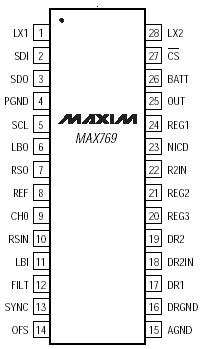 SpecificationsBATT, OUT, NICD, LBO, RSO to AGND......................-0.3V to +6V
REG1, REG2, OFS, REF, R2IN to AGND .....-0.3V to (OUT + 0.3V)
SCL, SDO, SDI, CS, SYNC, FILT, DR2IN,
CH0, LBI, RSIN to AGND......................-0.3V to (REG1 + 0.3V)
REG3 .....................................................-0.3V to (REG2 + 0.3V)
DR1, DR2 to DRGND ...............................-0.3V to (BATT + 0.3V)
PGND, DRGND to AGND.......................................-0.3V to +0.3V
LX1 to PGND ...........................................-0.3V to (OUT + 0.3V)
LX2 to PGND...........................................-0.3V to (BATT + 0.3V)
Continuous Power Dissipation (TA = +70)
QSOP (derate 8mW/ above +70)........................640mW
Operating Temperature Range .........................-40 to +85
Junction Temperature....................................................+150
Storage Temperature Range ...........................-65 to +165
Lead Temperature (soldering, 10sec) ...........................+300DescriptionThe MAX769 is a complete buck/boost power supply and monitoring system for two-way pagers or other lowpower digital communications devices. Few external components are required. Included on-chip MAX769 are:
· An 80mA output, synchronous-rectified, buck/boost
DC-DC converter with a digitally controlled +1.8V to
+4.9V output. The DC-DC converter is unique, since
it provides a regulated output for battery inputs that
are both less than and greater than the output voltage,
without using transformers.
· Three low-noise linear-regulator outputs
· Three DAC-controlled comparators for softwaredriven,
3-channel A/D conversion
· SPI™-compatible serial interface
· Reset and low-battery (LBO) warning outputs
· Charger for NiCd/NiMH, lithium battery, or storage
capacitor for RF PA power or system backup
· Two 1.8½ (typical), serial-controlled, open-drain
MOSFET switches for beeper or vibrator drive An evaluation kit for the MAX769 (MAX769EVKIT) is available to aid in design and prototyping.

 MAX769 Data Sheet