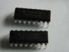
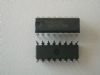
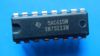
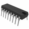
Pinout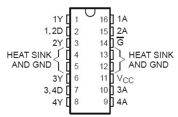 Specifications
Supply voltage range, VCC (see Note 1) . . . . . . . . . . . . . . . . . . . . . . . . . . . . . . . . . . . . . . . . . . . .0.3 V to 7 V
Input voltage, VI . . . . . . . . . . . . . . . . . . . . . . . . . . . . . . . . . . . . . . . . . . . . . . . . . . . . . . . . . . . . . . . . . . . . . .7 V
Output voltage range, VO . . . . . . . . . . . . . . . . . . . . . . . . . . . . . . . . . . . . . . . . . . . . . . . . . . . . . .0.3 V to 52 V
Output voltage, VO (inductive load) . . . . . . . . . . . . . . . . . . . . . . . . . . . . . . . . . . . . . . . . . . . . . . . . . . . . . . 43 V
Output clamp-diode terminal voltage range, VOK . . . . . . . . . . . . . . . . . . . . . . . . . . . . . . . . . . . .0.3 V to 52 V
Input current, II . . . . . . . . . . . . . . . . . . . . . . . . . . . . . . . . . . . . . . . . . . . . . . . . . . . . . . . . . . . . . . . . . . 15 mA
Peak sink output current, IOM(nonrepetitive, tw 3 0.1 ms) (see Note 2) . . . . . . . . . . . . . . . . . . . . . . . . . 1.5 A
(repetitive, tw 3 10 ms, duty cycle 3 50%) . . . . . . . . . . . . . . . . . . . . . . . . .1.4 A
Continuous sink output current, IO (see Note 2) . . . . . . . . . . . . . . . . . . . . . . . . . . . . . . . . . . . . . . . . . . . 1.3 A
Peak output clamp diode current, IOKM(nonrepetitive, tw 3 0.1 ms) (see Note 2) . . . . . . . . . . . . . . . . . . 1.5 A
(repetitive, tw 3 10 ms, duty cycle 3 50%) . . . . . . . . . . . . . . . . . .1.3 A
Continuous total dissipation at (or below) 25°C free-air temperature (see Note 3) . . . . . . . . . . . . . 2075 mW
Continuous total dissipation at (or below) 65°C case temperature (see Note 3) . . . . . . . . . . . . . . . .5000 mW
Operating case or virtual junction temperature range . . . . . . . . . . . . . . . . . . . . . . . . . . . . . . 55°C to 150°C
Storage temperature range . . . . . . . . . . . . . . . . . . . . . . . . . . . . . . . . . . . . . . . . . . . . . . . . . . 65°C to 150°C
Lead temperature 1,6 mm (1/16 inch) from case for 10 seconds . . . . . . . . . . . . . . . . . . . . . . . . . . . . . . . 260°C
NOTES: 1. All voltage values are with respect to the network GND (unless otherwise specified).
2. All four channels of this device may conduct rated current simultaneously; however, power dissipation average over a short time interval must fall within the continuous dissipation range.
3. For operation above 25°C free-air temperature, derate linearly at the rate of 16.6 mW/°C. For operation above 65°C case temperature, derate linearly at the rate of 59 mW/°C. To avoid exceeding the design maximum virtual junction temperature, these ratings should not be exceeded.
DescriptionThe SN75439 quadruple peripheral driver is designed for use in systems requiring high current, high voltage, and high load power. The device features two inverting and two noninverting open-collector outputs with a common-enable input that, when taken high, disables all four outputs. By pairing each inverting channel with a corresponding noninverting channel (such as channel 1 paired with channel 2 and channel 3 paired with channel 4), the device may be used as a complete full-step 4-phase dc stepper-motor driver using only two input logic control signals plus the enable signal, as shown in Figure 3. Other applications include driving relays, lamps, solenoids, motors, LEDs, transmission lines, hammers, and other high-power-demand loads. The SN75439 is characterized for operation from 0°C to 70°C.

 SN75439 Data Sheet