Features: ` 2`7 GHz Operating Frequency` Single 5V Supply` Low Power Consumption <1`3W`High Comparison Frequency : 20MHz` High Gain Phase Detector : 1mA/rad` Zero 'Dead Band' Phase Detector` Wide Range of RF and Reference Division Ratios` Programming by Dual Word Data TransferApplicationThe SP8...
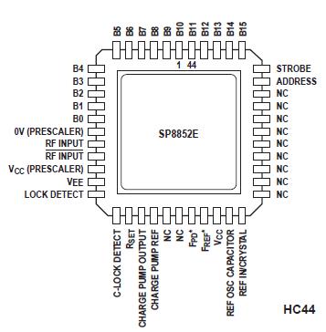
SP8852E: Features: ` 2`7 GHz Operating Frequency` Single 5V Supply` Low Power Consumption <1`3W`High Comparison Frequency : 20MHz` High Gain Phase Detector : 1mA/rad` Zero 'Dead Band' Phase Detector` Wide...
SeekIC Buyer Protection PLUS - newly updated for 2013!
268 Transactions
All payment methods are secure and covered by SeekIC Buyer Protection PLUS.
The SP8852E can operate with input frequencies up to 2·7GHz but to obtain optimum performance, good RF layout practices should be used. A suitable layout technique is to use double sided printed circuit board with through plated holes. Wherever possible the top surface on which the SP8852E is mounted should be left as a continuous sheet of copper to form a low impedance ground plane. The ground pins 12 and 16 should be connected directly to the ground plane.
Pins such as VCC and the unused RF input should be decoupled with chip capacitors mounted as close to the device pin as possible, with a direct connection to the ground plane; suitable values are 10nF for the power supplies and <1nF for the RF input pin (a lower value should be used sufficient to give good decoupling at the RF frequency of operation). A larger decoupling capacitor mounted as close as possible to pin 26 should be used to prevent modulation of VCC by the charge pump pulses. The RSET resistor should also be mounted close to the RSET pin to prevent noise pickup. The capacitor connected from the charge pump output should be a chip component with short connections to the SP8852E. All signals such as the programming inputs, RF IN, REFERENCE IN and the connections to the op-amp are best taken through the pc board adjacent to the SP8852D with through plated holes allowing connections to remote points without fragmenting the ground plane.

The SP8852E is one of a family of parallel load synthesisers containing all the elements apart from the loop amplifier to fabricate a PLL synthesis loop. Other parts in the series are the SP8854E which has hard wired reference counter programming and requires only a single 16-bit programming word, and the SP8855E which is fully programmable using hard wired links or switches.
The SP8852E is programmed using a 16-bit parallel data bus. Data can be stored in one of two internal buffers, selected by a single address bit on the input interface. In order to fully program the device, two 16-bit words are required, one to select the RF division ratio (A and M counters) and phase detector gain, and one to set the 10-bit reference divider count, phase detector state and sense. Once the reference divide ratio has been set, frequency changes can be made by a single 16-bit data load entry to the RF divider chain.