Features: • Over-Voltage Protection
• Programmable Over-Current Protection
• Voltage Mode Control
• Precision 1.3-V, ±1.6% Reference
• Drives N-Channel Switch and RectifierApplicationSetting the Current Limit
The current limit is set by comparing the voltage drop across the external high-side n-channel MOSFET with the voltage dropped across a sense resistor connected between VCC and
ICS. The ICS pin draws a constant current, and thus the equation governing the overcurrent threshold is: 170 A * R = ILimit * RMOSFET Once the on-state resistance of the MOSFET is known, R can be selected to set the desired current limit. One caution is in order: since the MOSFET will normally be quite warm, the resistance used in the equation should be the maximum resistance at elevated temperatures, not typical resistance at 25°C. The designer should also leave adequate margin above the normal output current, both to account for tolerances and noise in the IC, as well as to permit any initial high currents while charging output capacitors.
The Boost Diode
The application circuit shows the use of a 1N4148 diode for the boost circuit. This provides a low-cost component for this application. However, it may be advantageous in some circuits to use a Schottky diode instead. The difference is that the Schottky has less forward drop than the regular rectifier, and this in turn means a somewhat greater gate drive voltage for the external high-side MOSFET. For MOSFETs with high gate threshold and/or low transconductance, the additional gate drive may prove very beneficial in terms of the heating of the MOSFET, and in turn the efficiency of the converter. A ½-A, 30-V Schottky works well in this application.
Grounding
The Si9142 is provided with both analog and power ground pins (AGND and PGND, respectively). Because of the high gate drive currents the Si9142 can source, it is essential that
these two grounds be separated. PGND should be attached to the source of the external low-side MOSFET; AGND should be attached to the small-signal components of the circuit,
such as the timing resistor and the feedback resistor. Each of these grounds should be run back independently to the input line capacitors, to avoid ground loops.
Pinout SpecificationsVCC . . . . . . . . . . . . . . . . . . . . . . . . . . . . . . . . . . . . . . .4.75 V to 13.2 V
ROSC. . . . . . . . . . . . . . . . . . . . . . 100 kW (100 kHz) to 10 kW (1 MHz)
VL(out), (in) Capacitance . . . . . . . . . . . . . . . . . . . . . . . . . . . . . . . 4.7 mF
VL(out) Load . . . . . . . . . . . . . . . . . . . . . . . . . . . . . . . . . . . . . . . . . . . . 1 mA
VREF Capacitance . . . . . . . . . . . . . . . . . . . . . . . . . . . . . . . . . . .0.1 mF
VREF Load . . . . . . . . . . . . . . . . . . . . . . . . . . . . . . . . . . . . . . . . . . . . . 1 mA
Analog and Digital Inputs . . . . . . . . . . . . . . . . . . . . . . . . . . . . . 0 to VLDescriptionThe voltage mode, synchronous buck controller is designed for point-of-use dc/dc conversion in high performance server and desktop computers. High efficiency is accomplished at full load by driving high- and low-side n-channel MOSFETs. The input voltage range has been designed for 4.75 V to 13.2 V to allow use of either 5 V or 12 V. The 1-MHz switching
frequency combined with the 10-MHz error amplifier provides ultra-fast transient response necessary in a high performance microprocessor power supply.
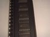
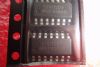
Si9142 is available in a 20-pin SOIC wide-body package and specified to operate over the commercial (0° to 70°C) temperature range.
A demo board, Si9142DB, is available.

 Si9142 Data Sheet