Amplifier Circuits-RF
The circuit diagram of a power MOSFET amplifier circuit with high frequency feature
Published:2011/7/13 19:49:00 Author:leo | Keyword: Power MOSFET amplifier, high frequency | From:SeekIC
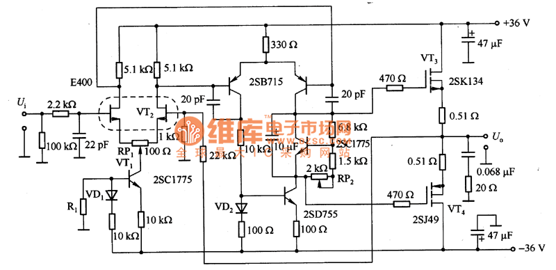
The picture 1 is a power MOSFET amplifier circuit with high frequency feature. In order to restrain the influence of the changes of power supply, it takes VT1 and VT2 to form the constant current circuit,while, VT3 and VT4 are end power amplifying circuit. Due to the influence of offset current, its drain currenthastemperature factors which is from positive to negative. Therefore, it uses RP2 to control the offset in order to set the drain current to 0.1 to 0.2 A, which passes through VT3 and VT4. And when its frequency is 1Hz to 800 kHz, the distortion is 0.04% per 1 kHz. At the same time, its output power is 40 W and the convert rate is 100V/μs.
Reprinted Url Of This Article:
http://www.seekic.com/circuit_diagram/Amplifier_Circuit/Amplifier_Circuits-RF/The_circuit_diagram_of_a_power_MOSFET_amplifier_circuit_with_high_frequency_feature.html
Print this Page | Comments | Reading(3)

Article Categories
power supply circuit
Amplifier Circuit
Basic Circuit
LED and Light Circuit
Sensor Circuit
Signal Processing
Electrical Equipment Circuit
Control Circuit
Remote Control Circuit
A/D-D/A Converter Circuit
Audio Circuit
Measuring and Test Circuit
Communication Circuit
Computer-Related Circuit
555 Circuit
Automotive Circuit
Repairing Circuit
Code: