
Index 210
the MP3 circuit
Published:2011/6/3 7:54:00 Author:Seven | Keyword: MP3 circuit
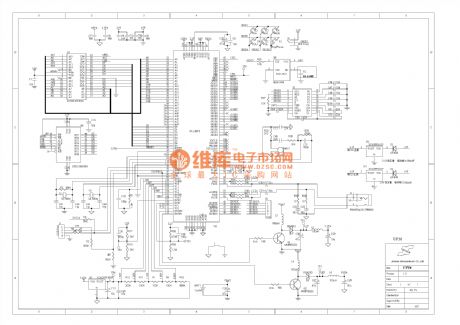
View full Circuit Diagram | Comments | Reading(684)
the MP3 circuit (4)
Published:2011/6/3 7:55:00 Author:Seven | Keyword: MP3 circuit

View full Circuit Diagram | Comments | Reading(696)
the MP3 circuit (5)
Published:2011/6/3 7:55:00 Author:Seven | Keyword: MP3 circuit
View full Circuit Diagram | Comments | Reading(1064)
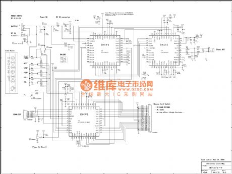
The MP3 circuit (7)
Published:2011/6/3 7:57:00 Author:Seven | Keyword: MP3 circuit

View full Circuit Diagram | Comments | Reading(636)
The MP3 circuit (8)
Published:2011/6/3 7:58:00 Author:Seven | Keyword: MP3 circuit
View full Circuit Diagram | Comments | Reading(592)
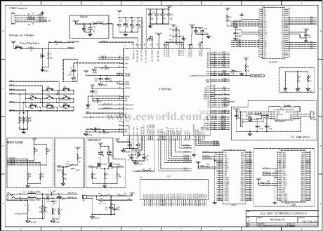
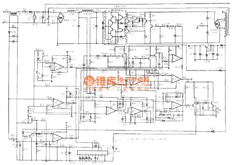
The MP3 hardware circuit (04)
Published:2011/6/3 8:20:00 Author:Seven | Keyword: MP3 hardware circuit
View full Circuit Diagram | Comments | Reading(656)
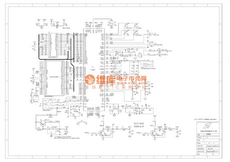
The MP3 hardware circuit (07)
Published:2011/6/3 9:07:00 Author:Seven | Keyword: hardware circuit
View full Circuit Diagram | Comments | Reading(560)
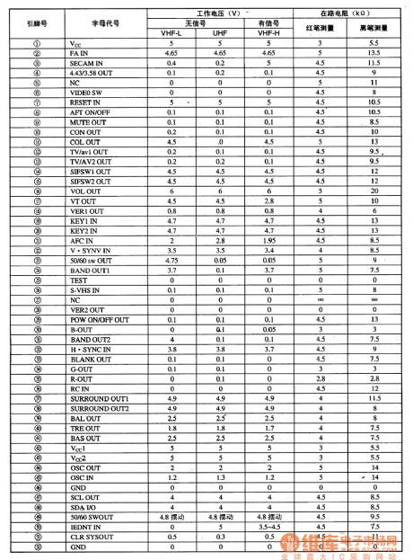
MN152810TTD5 single chip microcomputer integrated circuit
Published:2011/6/8 1:58:00 Author:Christina | Keyword: single chip, microcomputer, integrated circuit
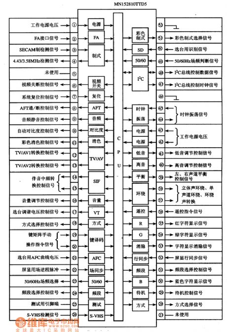
The MN152810TTD5 is designed as one kind of single chip microcomputer integrated circuit that is produced by the Panasonic corporation, and it can be used in the Konka and TCL color TVs.
1.Features
The MN152810TTD5 integrated circuit is composed of the central processing unit (CPU), the clock oscillating circuit, the reset control circuit, the key instruction decoder circuit, the I2C bus control circuit, the remote control command signal processing circuit, the screen display circuit, the audio adjusting control circuit, the integrated converter circuit and other control and auxiliary function circuits.
2.Pin functions and data
The MN152810TTD5 is in the 52-pin dual in-line package, the internal circuit block diagram and the signal flow are as shown in the figure, the pin-letter code and the data is as shown in the table.
The internal circuit block diagram and the signal flow of the MN152810TTD5
The pin-letter code and the data of the MN152810TTD5
(View)
View full Circuit Diagram | Comments | Reading(485)
The dual channel audio power amplifier circuit
Published:2011/6/3 23:59:00 Author:Seven | Keyword: dual channel, audio power amplifier
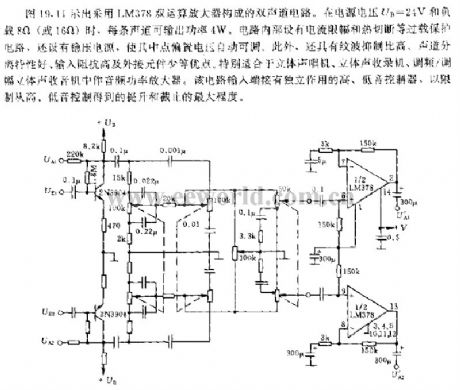
As shown in Figure 19.11, this is a dual channel circuit which consists of LM378 double computing amplifiers. When the voltage of power supply is 24v or the load resistance is 8Ω(or 15Ω),either channel can output power of 4W. Inside the circuit, there are current amplitude limit and heat cutting circuit, and there is the pressure steady power supply which allows the bias voltage to be auto-adjustable. Besides, it characterizes high wave limiting, good channel separation, high input impedance and few external elements. Etc. It is specially fit for stereo players, stereo recorders and so on.
(View)
View full Circuit Diagram | Comments | Reading(650)
The little device circuit of looking for cable break
Published:2011/6/1 21:47:00 Author:Seven | Keyword: device, cable break

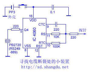
4060 and other parts consist a oscillator of 20KHZ, while the resistance capacitor of 100k and 200PF can change this frequency. Either Q3,Q4 and Q5 of IC can drive the LED or the electric buzzer, so that they can provide with necessary notices. This circuit is fixed in a metal case. When testing, we should hold the cable with one hand, and hold the tester with the other hand, besides, we should touch each pin with the probe in sequence, if the pin is linked, the separated capacitor will reduce the audio frequency. After that, we will do the same test to the other terminal. (View)
View full Circuit Diagram | Comments | Reading(612)
The electric thermometer of LED display
Published:2011/6/4 0:22:00 Author:Seven | Keyword: electric thermometer
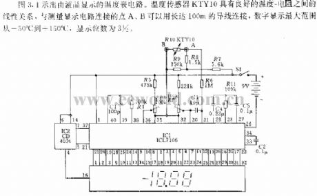
See as Figure 3.1, this is an electric thermometer circuit of LED display. The temperature sensor KTY10 has a good linear relationship between temperature and resistance, and it can be linked with the connecting points A and B of measuring display circuit with a 100m wire, the maximum range of the number display is from -50 to +150, the display bit is 3*1/2.
(View)
View full Circuit Diagram | Comments | Reading(1931)
The whole hotplate circuit (1)
Published:2011/6/3 8:37:00 Author:Seven | Keyword: hotplate circuit
View full Circuit Diagram | Comments | Reading(771)
The whole hotplate circuit (2)
Published:2011/6/3 8:37:00 Author:Seven | Keyword: hotplate circuit
View full Circuit Diagram | Comments | Reading(617)
The whole hotplate circuit (3)
Published:2011/6/3 8:38:00 Author:Seven | Keyword: hotplate circuit
View full Circuit Diagram | Comments | Reading(865)
The temperature data collecting system
Published:2011/6/4 0:14:00 Author:Seven | Keyword: temperature data

Notes: precision is 0.1%, 1% thin film resistance, Rplat is 1KΩ when it is 0℃.
Figure 1-4 the RID signal adjuster of digital linear plat resistance
The LT1027 in the circuit is a precise 5V parameter, and its temperature drifting is zppm/℃; the output source is 15mA, the lower is 10mA; the quick reaction is fabulous, which is used to input the parameter of A/D converters, and it is fixed with noise impedance pin; the long-term stabilization is good; when it is in the range of 0.1Hz~10Hz, the noise is lower than 1ppm.
(View)
View full Circuit Diagram | Comments | Reading(681)
The temperature compensation circuit
Published:2011/6/3 9:05:00 Author:Seven | Keyword: temperature compensation
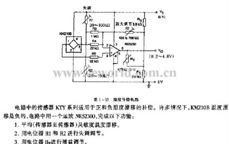
Figure 1-95 The temperature compensation circuitThe KTY sensors in the circuit is fit for positive and negative temperature drifting compensation. Under many conditions, the KMZ10B temperature drifting is negative, and an OP-Amp, NE52300, is used to to complete the following functions:1.average (from sensor to sensor) sensitivity temperature drifting; 2.the potentiometers of R1 and R2 are used to adjust maladjustment;3.the potentiometer RT is used to adjust the gains.
(View)
View full Circuit Diagram | Comments | Reading(764)
The thermometer circuit
Published:2011/6/3 8:35:00 Author:Seven | Keyword: thermometer circuit
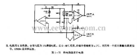
Notes: the circuit is fixed with a K thermal couple, the whole resistance is a 1% thin-film resistor. In the range of 0~60℃, the compensation precision of the cool pole is ±1℃. The temperature signal is output by another amplifier. LT0114 is a dual-four OP-Amp.Figure 1-75 the thermoelectric couple temperature circuit (View)
View full Circuit Diagram | Comments | Reading(657)
differential amplifier with light intensity change measurement circuit
Published:2011/5/23 22:46:00 Author:John | Keyword: light intensity change measurement
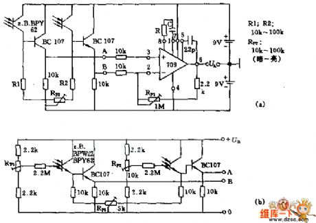
Figure (a) is a sensitive optical differential amplifier circuit. It has two identical photosensitive transistors (such as BPY62), being respectively connected to the op-amp 709 through its symmetry emitter follower BC107. Resistors R1 and R2 are determined according to the ambient brightness. Potentiometer RP2 can be used to adjust symmetry of two-input divider and operational amplifier. Potentiometer RP1 is used to adjust the amplification factor. The phototransistor base in this circuit opens. Figure (b) circuit has a good advantage of adapting to ambient light conditions.
(View)
View full Circuit Diagram | Comments | Reading(1830)
High input impedance instrumentation amplifier circuit
Published:2011/6/4 12:25:00 Author:John | Keyword: instrumentation amplifier
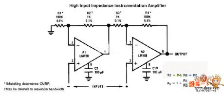
High input impedance instrumentation amplifier circuit is just as shown below.
(View)
View full Circuit Diagram | Comments | Reading(1856)
differential-input instrumentation amplifier
Published:2011/6/4 13:11:00 Author:John | Keyword: instrumentation amplifier
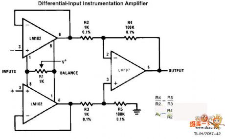

Differential-input instrumentation amplifier is just as shown below.
(View)
View full Circuit Diagram | Comments | Reading(4)
| Pages:210/250 At 20201202203204205206207208209210211212213214215216217218219220Under 20 |
Circuit Categories
power supply circuit
Amplifier Circuit
Basic Circuit
LED and Light Circuit
Sensor Circuit
Signal Processing
Electrical Equipment Circuit
Control Circuit
Remote Control Circuit
A/D-D/A Converter Circuit
Audio Circuit
Measuring and Test Circuit
Communication Circuit
Computer-Related Circuit
555 Circuit
Automotive Circuit
Repairing Circuit