
Index 200
Burr-Brown 3652 Isolation Amplifier Circuit
Published:2011/6/2 10:13:00 Author:Joyce | Keyword: Burr-Brown 3652, Isolation, Amplifier
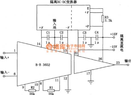
As shown in the figure is a circuit mainly composed of Burr-Brown 3652 isolation amplifier? Both isolated and insolated parts of 3652 are supplied by special power source 722,which generates two independent power supplies of ±15V , each being isolated with 50/60Hz ac power supply. And power source 722 itself is provided with ± 12V ac power supply. In some circumstances, the insolated part (which is connected with the output end) is supplied with bipolar dc power supply of 50/60Hz ac power supply, such as± 12V or±l5V power supply. But in no case would the isolated dc power be supplied with ac power. (View)
View full Circuit Diagram | Comments | Reading(744)
the isolated current - frequency conversion circuit to convert 4~20MA to 10KHZ
Published:2011/5/11 7:15:00 Author:Fiona | Keyword: the isolated current - frequency conversion, convert 4~20MA to 10KHZ,
Circuit Work
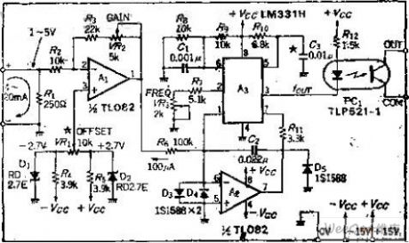
This circuit consists of two parts, namely, converting current - voltage section and the use of VF converting voltage into frequency by VF converter section.The current - voltage converter uses a 250Ω resistor R1, produces the voltage at R1's both ends, and then uses OP amplifier 1 to turn the voltage into 0 ~-10V, so the reverse magnification should be 2.5 times.
When current is 4MA, in order to make the output of A1 is 0, it must use home bias circuit. It can add the voltage at inverting input to form the home bias. If don't use the method of the home bias,put the in-phase input to ground. It also can be converted to 2 ~ 10KHZ frequency output when A1 magnification is 2.
V-F Converter uses NS company's LM331, its detailed structure has been introduced in the company's products' manuals .In order to improve linearity, add the OP amplifier A2, which is the current input type, full range is 0 ~ 100UA, therefore,according to the input voltage range, R5's resistance should be 100K, in the feedback loop, C2's role is to maintain Loop stability, the capacity is selected by range of the input signal.
(View)
View full Circuit Diagram | Comments | Reading(1755)
Circuit of Digitally Programmable Amplifier
Published:2011/6/3 9:45:00 Author:Michel | Keyword: Digitally Programmable Amplifier, Circuit
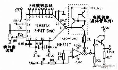
The circuit of digitally programmable amplifier uses the output current of the8-bit A/D converter NE5517 and current mirror device to controlhalf pluse of thedouble mutual guide operational amplifier NE5517.The maximum outputcurrent of NE5517 is 1mA.The circuit and microprocessor are fully compatible. (View)
View full Circuit Diagram | Comments | Reading(651)
Bootstrap Composite Amplifier Circuit
Published:2011/6/3 10:01:00 Author:Michel | Keyword: Bootstrap Composite, Amplifier Circuit
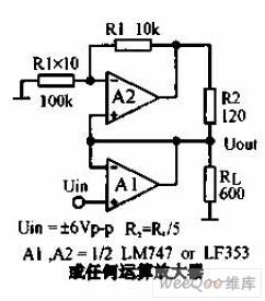
This circuit can realize that the load current is supplied by two op-amp output terminals together equally.A1 and A2 can choose LM747or LF353.Seen from the picture,A2's output voltage is equal to A's 1.1 times,R2 is equal to RL/5.Thus,the current thatflows through R2 is equal to half of the current thatflows through RL。 (View)
View full Circuit Diagram | Comments | Reading(1279)
Amplifier Circuit of FM Transmitter Main Frequency Power
Published:2011/6/5 0:42:00 Author:Michel | Keyword: FM Transmitter, Main Frequency Power, Amplifier Circuit
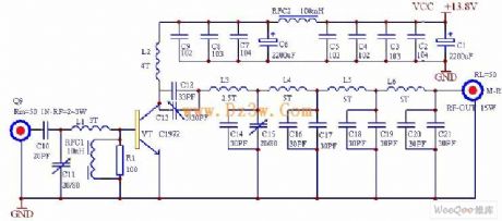
This power amplifier can extend 1-2W、88-108MHZ FM transmitter power to 10-15W.It uses single pipe c class amplifier and low-pass filter.It has higher conversion efficiency andstrong suppersion of considered wave.
Principle Figure
The circuit is showed as above.It adopts high-power transmitting tube C1972 and parameters are as follows:175MHZ,4A,25W,power gain ≥8.5db.As the pictures'parameters,the work center frequency is about 98MHZ.When the input radio-frequency power is about 2W,the rating output can reach 15W.The center frequency of former stage adjusts part of components to make sure that any frequency port among 88~108MHZ can reach rating value when it outputs. (View)
View full Circuit Diagram | Comments | Reading(3698)
Automatic Switching of AC and DC Input Circuit
Published:2011/5/17 6:01:00 Author:Joyce | Keyword: Automatic Switching, of AC and DC, Input
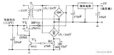
The following graph is the automatic switching of AC and DC circuit .After being depressurized by transformer T1, the electric supply will be output after rectifying, filtering and voltage stabilization to make the load work. Meanwhile, another route will go to the base of VT2 after going through a direct voltage produced by rectifying and filtering and being divided by RP. So VT2 will break over and VT1 will cut off. When the electric supply breaks off, VT2 will cut off and MOSFET VT1 will break over. Storage battery will supply the voltage-stabilizing circuit through VT1 andoutput stable direct voltage for the load. Due to the application of MOSFET to conduct fast electronic switching, this circuit has achieved the purpose of uninterrupted power supply. (View)
View full Circuit Diagram | Comments | Reading(691)
MAX1916 Output Parallel Connection Circuit
Published:2011/5/17 5:59:00 Author:Joyce | Keyword: MAX1916, Output, Parallel Connection
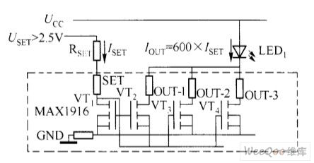
The drain source resistance of MAX1916 is set not to exceed 50Ω in the whole temperature range. A GaAsP - LED with a working current of 2mA guarantees the minimum voltage needed in proper function is UF + 1 00mV. Input voltage of 2.7 V can keep the working voltage of GaAsP - LED to2.7 V. In order to acquire lower differential pressure and higher output current, one can connect three ways of the output of MAX1916 in parallel to constitute a current source with 600A/A mirror coefficient . MAX1916 output parallel connection circuit is shown in the graph, and the drain source resistance is50/3 = 16.61 Ω (Max) if connected in this way. This kind of connectionallows the current of a single white light LED to reach 20mA above with 3V power supply,so as to meet current requirements in blacklight of products like portable mobile phones.Thevoltage source used to set the end-point current can be supplied by a main power with a strong load capacity alone,such as on mobile phones. USET can be supplied with a low noise + 2.8 V power source of RF circuit. If it is supplied directly by single lithium ion battery, MAX1916 can be applied to driveGaAsP - LED with relatively low forward voltage , and resort to other drive schemes for white light InGaN - LED with high forward voltage. Because when it is supplied by the lithium ion battery, as the discharge goes on,the input voltage may fail to reach the required bias voltage of the white light LED. (View)
View full Circuit Diagram | Comments | Reading(744)
Soft Start of the Power Supply Circuit Composed of L200
Published:2011/5/17 6:02:00 Author:Joyce | Keyword: Soft Start of, the Power Supply, Composed of L200
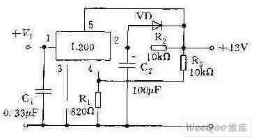
As shown in figure below,it starts using the maximum output current regulation and control of foot 2 of L200.In this way, C2 would prevent voltage jump of foot2 in starting up, and L200 remains the state ofsmallest output current. As foot5 charges C2 through R2,the output voltage of L200 would gradually increase.According to the component parameters in the graph, it takes 7s for the output voltage to reach the rated value.One also can delay the connection of L200 benchmark end foot 4 and R1 to achieve the purpose of soft start.
(View)
View full Circuit Diagram | Comments | Reading(1029)
Power Factor Measure Circuit
Published:2011/5/20 18:49:00 Author:leo | Keyword: Power Factor Measure Circuit, CD4066
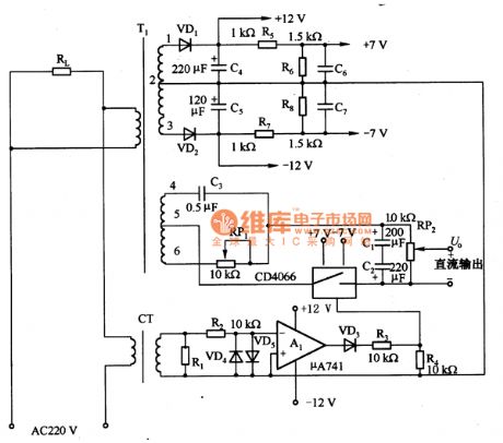
The picture is a power factor measure circuit. Power factor is used to show the phase relationship between voltage and electronic current. In the circuit, the voltage of T1 secondary 4 to 6 is used as the DC voltage sample and the secondary current of current transformer is used as the current sample. The current sample signal is amplified through A1 to control the analog switch CD4066 and takes effect with voltage sample, and then positive and negative DC voltages are generated.
(View)
View full Circuit Diagram | Comments | Reading(3662)
DC meter protection amplification circuit made by LM10 and others
Published:2011/5/20 18:52:00 Author:leo | Keyword: C meter protection amplification circuit, LM10
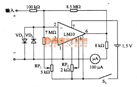
The picture 1 is a DC meter protection amplification circuit and is made up of LM10 and others. It is a kind of DC meter protection amplification circuit which needs to work in the temperature of 15 to 55 centigrade. The sensitivity of full scale is lOmV/l0nA. RP2 is used to set to zero. And the based voltage of setting zero is decided by the based voltage in the LM10 and does not affect by the voltage of power supply. RP1 is used to set bias current and VD1 and VD2 are the protecting diodes of LM10. The power supply of this circuit is 1.5 V and the current sinking is about 0.5mA.
(View)
View full Circuit Diagram | Comments | Reading(1038)
The circuit diagram only permitting small DC singal voltage
Published:2011/5/20 19:56:00 Author:leo | Keyword: circuit diagram, small DC singal voltage
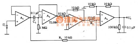
As what is shown in the picture, this is a circuit that only permits the small DC electronic current to pass through. If the inputting signal Ui is a sinusoidal waveform with the asymmetric peak value, and if the VFM is 11V and negative peak is -9 V, this waveform has small DC voltage. In some application, it needs to output the small DC signals and eliminate the AC signals which common low-pass filter cannot do but this circuit can make it come true. In this circuit, the buffer A1 buffers the inputting signals, and then the voltage of the buffered signals comes through the capacitor C1 and is coupled to a complete AC waveform voltage U1. (View)
View full Circuit Diagram | Comments | Reading(746)
The circuit diagram of amplifier made up of μA709
Published:2011/6/8 20:53:00 Author:leo | Keyword: The circuit diagram of amplifier made up of μA709 , A709
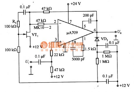
Picture 1 shows an amplifier made up ofμA709 and others. In this circuit, VT1 forms step attenuator which is regarded as a control part of automatically gaining. It is used to rectify and feedback the peak valve of its gate bias and connected to the negative feedback circuit of operating amplifierμA709.Feeback generated through R1 is used to make up nonlinear distortion of VT1. (View)
View full Circuit Diagram | Comments | Reading(849)
FR660-the integrated microcomputer circuit of communication single door
Published:2011/5/17 20:53:00 Author:Borg | Keyword: microcomputer, communication single door
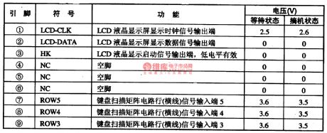
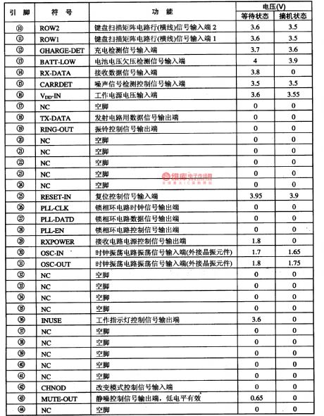
GD9815-5 is an integrated microcomputer circuit of communication single door, which is used in wireless phones.1.function featuresFR660 contains sub-circuits of cell phone signal launch/receiving, ring control, charging detection, noise detection, generating of two-tone multiple-frequency DTMF signals, coding data signal generating, pulse dialing generating, out-layer series plugs and series communication plugs, with which we can detect dialing width and decodes, we can also use it to save the encoding information.
2.pin functions and data
(View)
View full Circuit Diagram | Comments | Reading(540)
Low cost high precision automatic shift proportion amp circuit
Published:2011/6/7 3:37:00 Author:Fiona | Keyword: Low cost high precision, automatic shift proportion amp
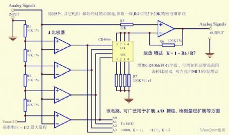
In addition to R5, the other resistance is best to be carefully selected, has the same parameters,2 20K precision resistor in series can be instead of R4.It can increase the control gain range to increase the number of CD4066 and R7. Remove the comparator, It can directly control gain by the MCU. The circuit can be widely used in expansion A / D accuracy, detection range extension and so on. (View)
View full Circuit Diagram | Comments | Reading(558)
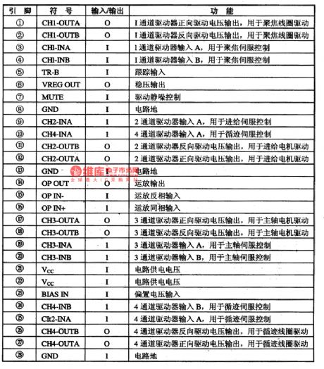
BA5902FP-laser head servo-driven integrated circuit
Published:2011/5/18 22:13:00 Author:Borg | Keyword: laser head, servo-driven
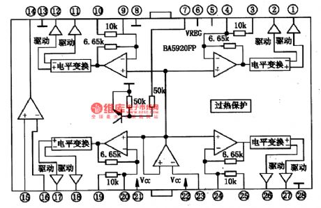
BA6196FP is a motor-driven integrated circuit produced by Toyo Corp., which is used in laser heads to laser players.1.The internal circuitBA6196FP contains 4-channel BTL drive circuit and drive silence-noise control circuit, whose internal circuit is shown in Figure 1.
Figure 1 the internal circuit of BA5902FP
pin functions BA5902FP is in 28-lead dual in-line package, whose pin functions are listed in Table 1.
Table 1 pin functions and data of BA5902FP chips (View)
View full Circuit Diagram | Comments | Reading(660)
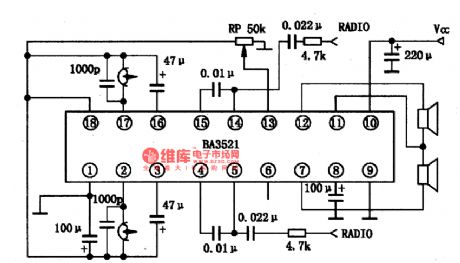
BA3521-the integrated circuit of stereo reproducing single door
Published:2011/6/10 3:23:00 Author:Borg | Keyword: integrated circuit, single door
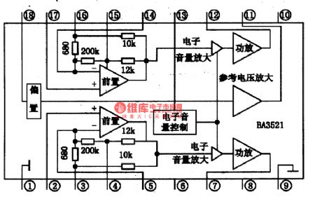

EM78811 is an integrated circuit of stereo reproducing single door, which is widely used in walk-man and portable radios.1.The internal circuit and pin functions of BA3521BA3521 contains 2-channel pre-stage, 2-channel headphone power amplifier, power volume control circuit and mute circuit while power supply is on. The internal circuit of is as shown in Figure 1. It is in 18-lead dual in-line package, whose pin functions are listed in Table 1.
2.Main parameters of BA35213.The typical application circuit of BA3521
(View)
View full Circuit Diagram | Comments | Reading(1218)
AN8813NSBS-the integrated 4-channel drive circuit
Published:2011/5/18 22:20:00 Author:Borg | Keyword: integrated, 4-channel, drive circuit
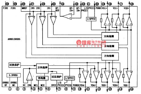

AN8813NSBS is an integrated 4-channel laser head drive circuit which is produced by Panasonic specially for DVD core. It is widely used in Panasonic DVD players.1.function featuresAN8813NSBS can convert loading control signals and servo control signals of focusing, tracking and feeding into drive voltage, by which is can load motors, feed motors, focus and track coils. The internal circuit of it is as shown in Figure 1.
2.pin functionsAN8813NSBS is in flat 30-lead package, whose pin functions are listed in Table 1.
(View)
View full Circuit Diagram | Comments | Reading(547)
AN7120 2.lW-the integrated circuit of audio power amplifier
Published:2011/5/19 21:31:00 Author:Borg | Keyword: integrated circuit, audio power amplifier
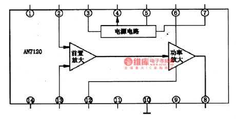
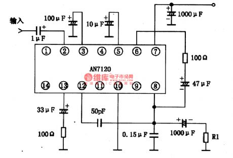
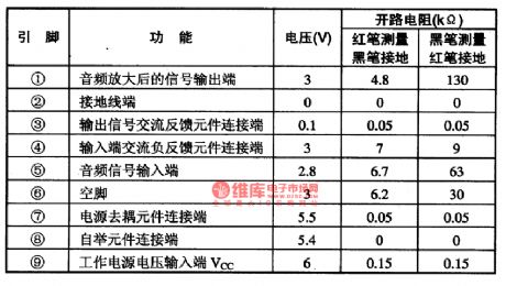
AN7120 is a integrated line circuit of 2.lW audio power amplifier which is produced by Panasonic. It is used in radios, recorders, record-players and computer stereos as the output stage.1.The internal circuit and pin functions AN7120 characterizes with low working voltage, large output power, trivial AC distortion, low engine starting noise and stable work even when the power supply is sharply changing. The pin of ④ can output stable voltage for pre-stage or something out of the circuit. The IC is in 14-lead dual in-line package.
Table 1 pin functions and data of AN7120
(View)
View full Circuit Diagram | Comments | Reading(945)
AN711O,AN711OEl.2W-the integrated circuit of audio power amplifier
Published:2011/5/19 21:32:00 Author:Borg | Keyword: integrated circuit, audio power amplifier
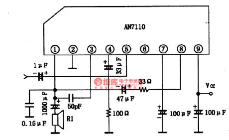
1.the internal circuit and pin functions of AN711O/EThe internal equivalent circuit of AN711O/E is shown in Figure 1, the IC is in 9-lead single in-line package, and the pin functions and data are listed in Table 1.
Figure 1 the internal equivalent circuit of AN711O
2.principle parameters of AN711O(1) Limiting parameter. Power supply voltage Vcc=18V,power supply current Icc=2A,Power consumption PD=1.5W.(2)principle parametersWhen Vcc=9V,RL=8Ω,f=1KHz,Ta=25℃, there are the following parameters.3.the typical application circuit of AN711OThe typical application of AN711O/E is shown in Figure 2.
(View)
View full Circuit Diagram | Comments | Reading(801)
Use common components high-precision polarity conversion circuit
Published:2011/6/3 11:00:00 Author:Fiona | Keyword: Use common components, high-precision, polarity conversion
circuit work
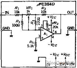
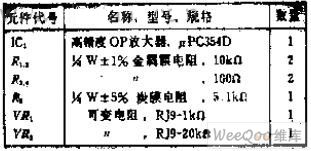
Because the OP amp loop gain mainly depends on the ratio of input resistance and the feedback resistance .So resistance has margin of error, the gain will be a corresponding errors.To get more than four-digit precision, we need high-precision resistor. The resistor R3, R4 used to narrow the variable scope of VR1 is 1 / 100 of the R1, R2 resistance, so that you can compensate the deviation of the resistance, in fact,R1 is 9.9 k ohms , R2 is 10.1 k ohms.This worst case is very small, so it is enough that the adjustable range of the VR1 is ± 1%.
Component Selection
(View)
View full Circuit Diagram | Comments | Reading(557)
| Pages:200/250 At 20181182183184185186187188189190191192193194195196197198199200Under 20 |
Circuit Categories
power supply circuit
Amplifier Circuit
Basic Circuit
LED and Light Circuit
Sensor Circuit
Signal Processing
Electrical Equipment Circuit
Control Circuit
Remote Control Circuit
A/D-D/A Converter Circuit
Audio Circuit
Measuring and Test Circuit
Communication Circuit
Computer-Related Circuit
555 Circuit
Automotive Circuit
Repairing Circuit