
Index 187
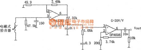
low noise and hifi RIA preamplifier (OPA606) circuit
Published:2011/6/30 2:19:00 Author:chopper | Keyword: low noise, hifi, RIA, preamplifier
(View)
View full Circuit Diagram | Comments | Reading(981)
OPA502 hifi music center amplifition circuit
Published:2011/6/30 2:19:00 Author:chopper | Keyword: hifi, music center, amplifition circuit
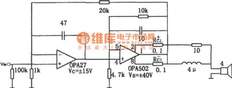
The picture is a hifi music center amplifition circuit.This circuit adopts low noise precise op-amp OPA27 as a preamplifier.The greatest output power can reach 150W.When the output power is 50W and frequency is 20KHz,its total harmonic distortion is 0.02%.And when the frequency is 1KHz,the total harmonic distortion is 0.002%.OPA27 can improve its input impedance by using in-phase input method.When supply voltage is ±15V,the dynamic range of linearity is ±12V.
(View)
View full Circuit Diagram | Comments | Reading(935)
AC power detecting circuit made by MD7750
Published:2011/6/21 8:10:00 Author:leo | Keyword: AC power detecting circuit made by MD7750, AD7750
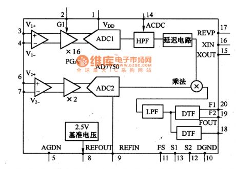
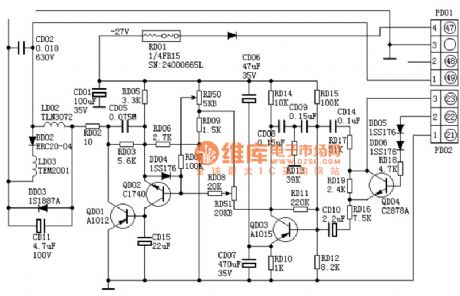
As picture a and b show, this is a AC power detecting circuit made by MD7750.AC power is the product of multiplication of current value and voltage value. This circuit is used to detect the power of 50 Hz single phase AC circuit. It can adopt common A/D converter but here it takes special A/D converter AD7750 with power detecting function.
The voltage value and current value can be tested on the high voltage terminal, therefore, current and voltage signals can be detected by voltage divider.AD7750 has two input terminals which are current signals terminal V1 and voltage signals terminal V2. These two terminals are different from each other. (View)
View full Circuit Diagram | Comments | Reading(739)
Pressure sensor with filter and amplification circuit
Published:2011/6/26 8:34:00 Author:Fiona | Keyword: Pressure sensor, filter and amplification
MAX4471 is amplifier.MAX9028 is the MAXIM company's low power comparator.Filter circuit uses band-pass filter composed of MAX267(allowing 0.8 ~ 38Hz signal through),filters out the DC component of the signal,power,the high-frequency noise and frequency interference of the skin with the cuff friction,then further amplifies through the MAX4471,gets the matching chip voltage signal into the ADC2,monitors the AC component of blood pressure.While the signal is converted into pulse signals through a low-power comparator MAX9028 to trigger ADC1 work.
(View)
View full Circuit Diagram | Comments | Reading(676)
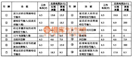
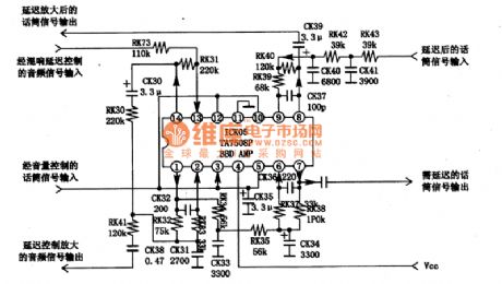
TA7508P karaoke reverberation audio amplifition integrated cirucit
Published:2011/6/17 6:30:00 Author:chopper | Keyword: karaoke, reverberation audio, amplifition, integrated cirucit
TA7508P is a audio amplifition integrated circuit produced by Company TOSHIBA,and it is used as a reverberant acoustics signal generated by amplifition and delay on Konka BT5001 RPTV. TA7508 is one model of the TA7508P integrated circuits whose power is greater than TA7508 and it adopts 35V power supply,while TA7508 adopts 12V power supply.The functions of pins of the two are the same.TA7508 integrated circuit is applied to Konka BT5001 RPTV.Its function and data of integrated circuit is shown as chart 1.
(View)
View full Circuit Diagram | Comments | Reading(733)
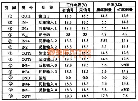
TA7508 quad operational amplifier integrated circuit
Published:2011/6/16 0:52:00 Author:chopper | Keyword: quad operational, amplifier, integrated circuit
TA7508 is a quad operational amplifier integrated circuit.It belongs to general device.and it is applied to TV acoustics,music center and so on.1.The inner circuit and the function of pins of TA7508 TA7508 integrated package includes four same operational amplification circuit.The inner circuit is shown as the picture 1.This IC adopts the structure of 14 pins biserial plastic package.And it is applied to the Changhong NC-3 cassette mechanism colorcast karaoke circuit.The function and data of pins of integrated circuitare shown as chart 1.
2.TA7508 typical application circuitTA7508 integrated package is applied to the Changhong NC-3 cassette mechanism colorcast karaoke circuit.Its typical application circuit is shown as picture 2. (View)
View full Circuit Diagram | Comments | Reading(790)
Consisting of uPC1378H field output circuit
Published:2011/6/28 3:14:00 Author:Fiona | Keyword: Consisting of uPC1378H, field output
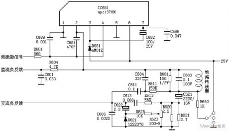
uPC1378H pin functions:
1 pin : 0V - ground
2 pin : 12V - output field
3 pin : 26V - bootstrap voltage input
4 pin : 0.8V-- field drive signal input
5pin : 0V - external decoupling capacitor
6 pin : 26V - power input
7 pin : 1.8V-- bootstrap voltage output
(View)
View full Circuit Diagram | Comments | Reading(2801)
AN5276 dual-channel audio power amplifier integrated circuit
Published:2011/6/30 3:55:00 Author:Christina | Keyword: dual-channel, audio power amplifier, integrated circuit
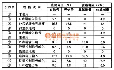
The AN5276 is designed as one kind of dual-channel audio power amplifier integrated circuit that can be used in the Panasonic, Sharp and Hitachi TV sets or the sound system's amplifier of the FuRi large screen color TV.
1.Features
The AN5276 is composed of two channels of power amplifier circuits with the same function, the static noise control circuit, the standby control circuit and the over temperature and short-circuit protection circuit, the output power of every channel is about 12.5W.
2.Pin functions and data
The AN5276 uses the 12-pin single row package, the pin functions and data are as shown in table 1.
Table 1 The pin functions and data of the AN5276
(View)
View full Circuit Diagram | Comments | Reading(1545)
AN5274 dual-channel audio power amplifier integrated circuit
Published:2011/6/30 3:58:00 Author:Christina | Keyword: dual-channel, audio power, amplifier, integrated circuit
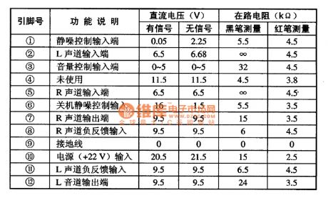
The AN5274 is designed as one kind of dual-channel audio power amplifier integrated circuit which is produced by the Panasonic company, and it can be used in the large screen color TVs and the home audio equipments.
1.Features
The AN5274 is composed of two channels of power amplifier circuits with the same function, the static noise control circuit, the standby control circuit and the over temperature and short-circuit protection circuit, the output power of every channel is about 4W.
2.Pin functions and data
The AN5274 uses the 12-pin single row package, the pin functions and data are as shown in table 1.
Table 1 The pin functions and data of the AN5274
(View)
View full Circuit Diagram | Comments | Reading(990)
AN5273 dual-channel audio power amplifier integrated circuit
Published:2011/6/30 4:06:00 Author:Christina | Keyword: dual-channel, audio power, amplifier, integrated circuit
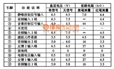
The AN5273 is designed as one kind of dual-channel audio power amplifier integrated circuit which is produced by the Panasonic company, and it can be used in the large screen color TVs and the home audio equipments.
1.Features
The AN5273 is composed of two channels of power amplifier circuits with the same function, the static noise control circuit, the electronic volume control circuit and the over temperature and short-circuit protection circuit, the output power of every channel is about 5W.
2.Pin functions and data
The AN5273 uses the 12-pin single row package, the pin functions and data are as shown in table 1.
Table 1 The pin functions and data of the AN5273
(View)
View full Circuit Diagram | Comments | Reading(817)
AN5265 audio power amplifier integrated circuit
Published:2011/6/30 4:19:00 Author:Christina | Keyword: audio power, amplifier, integrated circuit
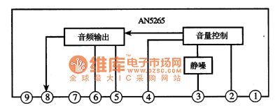
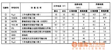
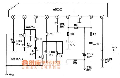
The AN5265 audio power amplifier integrated circuit is produced by the Panasonic company that can be used in a variety of sound systems as the power amplifier.
1.The internal circuit block diagram
The AN5265 is composed of the electronic volume control circuit, the static noise control circuit and the audio output circuit.etc. The internal circuit block diagram is as shown in figure 1.
Figure 1 The internal circuit block diagram of AN5265
2.Pin functions and data
The AN5265 uses the single row 9-pin package, the pin functions and data are as shown in table 1.
Table 1 The pin functions and data of the AN5265
3.Typical application circuit
The typical application circuit is as shown in figure 2.
(View)
View full Circuit Diagram | Comments | Reading(8301)
resistance error gauge circuit with IC
Published:2011/6/18 10:15:00 Author:Nancy | Keyword: resistance error gauge, IC
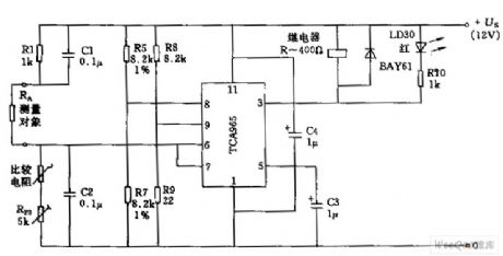
The circuit uses voltage divider R5 and R7 to form a window descriminator connected to pin 8 of TCA965. The width of the window is adjusted by the voltage at pin 9. The width of the window can be set as 64mV(+US=12)by appropriately setting the value of R9 as 22Ω. Under small window width,the measurement accuracy is relative to the error of the R6 and R7. Since the circuit TCA963 output has 50mA load current, it can directly drive relay coil or LED. (View)
View full Circuit Diagram | Comments | Reading(675)
preamplifer circuit with high impedance
Published:2011/6/18 10:29:00 Author:Nancy | Keyword: high impedance, preamplifer
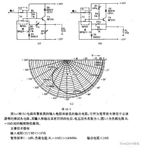
Figure (a) and (b) has very high input resistor and very low output resistor and can be used as wideband amplifier for test head circuit such as oscilloscope, the input and output have the same electric potential, the voltage amplification factor is 1. Figure (c) is the amplitude and phase characteristic curve when load resistor RL equals to 50Ω.
Main technical data:input resistor (25℃)﹥109Ωwideband frequency (-3 dB, load resistor RL=50Ω)﹥100MHz output resistor﹤10Ω (View)
View full Circuit Diagram | Comments | Reading(702)
Gain or programming amplifier circuit
Published:2011/6/20 8:31:00 Author:Nancy | Keyword: Gain amplifier, programming amplifier
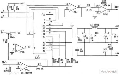
The circuit shown is a wide input range amplifier composed by PGA103. The 11.3kΩ and 102kΩ resistors form the voltage division circuit, the divider ratio is about 1/10, when the input voltage is 120V, the voltage added to PGA103 input after division is only 12V, therefore wide voltage input is available. Meanwhile, didoe D1, D2(1N4148) use as two-way clamp, making the input voltage of PGA103 ±15 to 士0.7V. (View)
View full Circuit Diagram | Comments | Reading(710)
Dual-tone phone dial monitor circuit
Published:2011/6/29 1:58:00 Author:Fiona | Keyword: Dual-tone phone, dial monitor
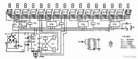
Dual-tone phone dial monitor circuit is shown as below,this circuit is composed of fixed-pole circuit(D1~D4,R1,R2,DW),dual audio decoding circuit(MC145436),BCD code conversion circuit (inverter A,B,two-input gates C,D),shift display circuit (IC4,IC5,IC3,IC2,IC6 ~ IC21) and other parts. (View)
View full Circuit Diagram | Comments | Reading(847)
The same line automatic recording attached device circuit
Published:2011/6/29 2:45:00 Author:Fiona | Keyword: The same line, automatic recording
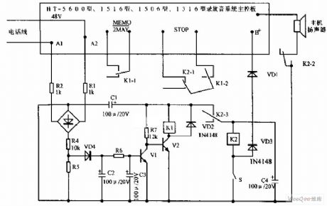
The same line automatic recording attached device circuit is shown as below, the same line automatic recording attached device can be easily used at different types of domestic and international recording telephone and answering machine.Due to be limited by the original machine power and the original machine volume,it is best to choose small sensitive relay, such as the Nissan SV-5 and M4-5.The device is best to be added at automatic recording tape telephone,modification effect is not obvious on IC language chip type recording telephone.
(View)
View full Circuit Diagram | Comments | Reading(749)
Low frequency adjustment circuit
Published:2011/6/30 20:16:00 Author:TaoXi | Keyword: Low frequency, adjustment circuit
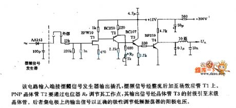
The output port of this circuit is connected with the output jack of the wobbling frequency signal generator, the wobbling frequency signal is rectified and adds to the Mosfet T1. The PNP transistor T2 adjusts the operating point through the potentiometer RP, the output signal is led to the final stage transistor through the transistor T3. The output signal of the final stage transistor's collector adjusts the low frequency oscillator's anode voltage with correct polarity.
(View)
View full Circuit Diagram | Comments | Reading(712)
Toshiba 2500XH correction circuit
Published:2011/6/27 21:12:00 Author:chopper | Keyword: Toshiba, correction circuit
View full Circuit Diagram | Comments | Reading(740)
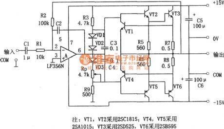
7W audio power amplifier (LF356) circuit
Published:2011/6/22 20:25:00 Author:chopper | Keyword: 7W, audio power, amplifier
(View)
View full Circuit Diagram | Comments | Reading(2141)
audio power amplifier (OPA604) circuit of high-performance but samll power
Published:2011/6/29 0:32:00 Author:chopper | Keyword: audio power amplifier, high-performance, samll power
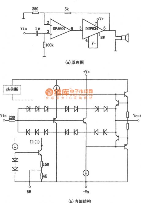
The picture is a audio power amplifition circuit of high-performance but samll power.The preceding stage of circuit adopts FET hi-fi op-amp OPA604,and the backward stage adopts high-speed buffer BUF634, and the voltage will cascade negative feedback between the dual-stage amplifier.The volatge amplifition time is detemined by two resistors(5kΩ and 250Ω) of feedback branch,and their values are 1+5kΩ/250Ω≈21 times.BUF634 is high-speed buffer.The internal structure simplified circuit is shown as picture (b).
(View)
View full Circuit Diagram | Comments | Reading(1209)
| Pages:187/250 At 20181182183184185186187188189190191192193194195196197198199200Under 20 |
Circuit Categories
power supply circuit
Amplifier Circuit
Basic Circuit
LED and Light Circuit
Sensor Circuit
Signal Processing
Electrical Equipment Circuit
Control Circuit
Remote Control Circuit
A/D-D/A Converter Circuit
Audio Circuit
Measuring and Test Circuit
Communication Circuit
Computer-Related Circuit
555 Circuit
Automotive Circuit
Repairing Circuit