
Index 196
The 6sn7 classic wiring circuit
Published:2011/6/20 22:25:00 Author:Seven | Keyword: classic wiring circuit
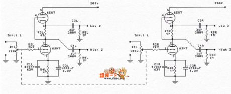
The 6sn7 classic wiring circuit is shown as above. (View)
View full Circuit Diagram | Comments | Reading(1237)
The FU-50 single terminal circuit
Published:2011/6/20 22:40:00 Author:Seven | Keyword: single terminal
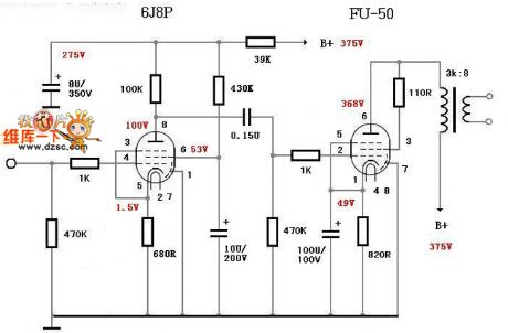
The FU-50 single terminal circuit is shown as above. (View)
View full Circuit Diagram | Comments | Reading(3128)
The FU29 push-pull circuit
Published:2011/6/20 22:41:00 Author:Seven | Keyword: push-pull circuit
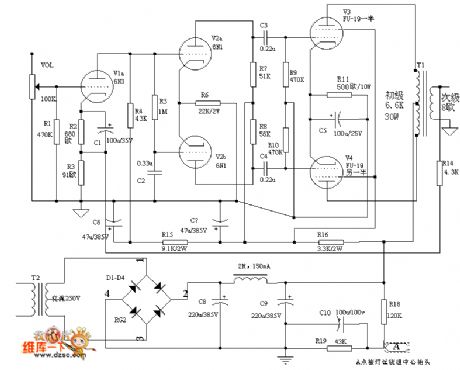
The FU29 push-pull circuit is shown as above. (View)
View full Circuit Diagram | Comments | Reading(3939)
The 6N11+6N5 headphone amplifier circuit
Published:2011/6/21 2:07:00 Author:Seven | Keyword: headphone amplifier
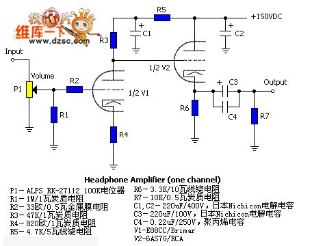
The 6N11+6N5 headphone amplifier circuit is shown as above. (View)
View full Circuit Diagram | Comments | Reading(2916)
The adv7175 and adv7176 digital video encoding integrated video amplifier circuit
Published:2011/6/19 20:46:00 Author:qqtang | Keyword: video encoding, integrated video amplifier
The adv7175 and adv7176 digital video encoding integrated video amplifier circuit in shown in the figure.
(View)
View full Circuit Diagram | Comments | Reading(785)
Operational Amplifier Absorber Circuit
Published:2011/6/14 23:35:00 Author:Robert | Keyword: Operational Amplifier, Absorber
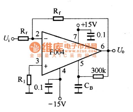
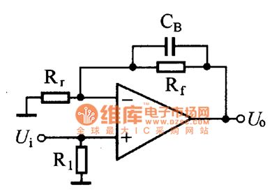

The operational amplifier is a device with high gain. By adding deep negative feedback when using, the operational amplifier can get good closed loop characteristic. But the negative feedback circuit always bring phaseshift for high-frequency signals. When this phaseshift get to 180。it would make the negative feedback to be positive feedback, so it would generate parasitic self-oscillation to make the opertaional amplifier unable to work normally. In the low frequency the self-oscillation is mostly generated by common power coupling. This case can be solved by strengthening the decoupling. In the high frequency the self-oscillation is solved by corresponding phase compensation method. (View)
View full Circuit Diagram | Comments | Reading(617)
CD4069 six NOT gates integrated circuit
Published:2011/6/13 6:16:00 Author:Christina | Keyword: six NOT gates, integrated circuit
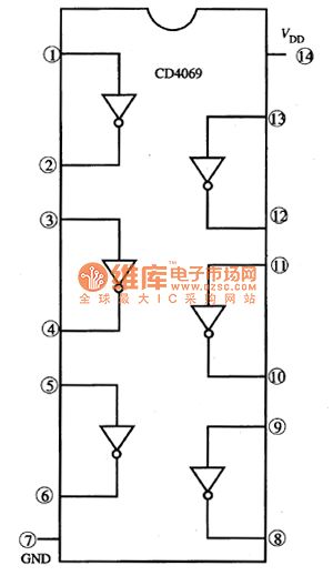
The CD4069 is designed as one kind of CMOS general six NOT gates integrated circuit that can be used in wide range of applications, and it can be used to form the oscillator, buffer, trigger and inverter.etc.
1.The internal circuit block diagram
The CD4069 is in the 14-pin dual-row DIP package, the internal circuit block diagram is as shown in figure 1.
Figure 1 The internal circuit block diagram of the CD4069
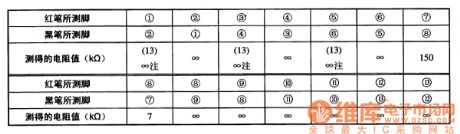
2.The open resistance between the pins
The open resistance between the pins of the CD4069 which is measured by the 500 multimeter is as shown in figure 1.
Figure 1 The open resistance between the pins of the CD4069
PS: When you are measuring this resistance, you use the black pen to touch the pin, when the pin recovers the normal position, some times the resistance is 13KΩ, and if you disconnect the pen, the resistance is ∞. (View)
View full Circuit Diagram | Comments | Reading(1139)
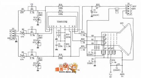
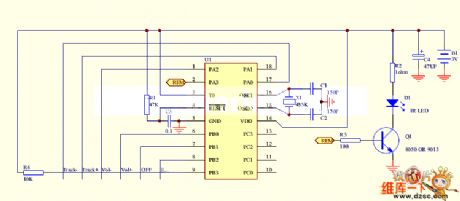
TV remote control 14 circuit
Published:2011/6/21 8:05:00 Author:John | Keyword: TV remote control

View full Circuit Diagram | Comments | Reading(678)
TV remote control 09 circuit
Published:2011/6/21 9:07:00 Author:John | Keyword: TV remote control
View full Circuit Diagram | Comments | Reading(631)
TV remote control 10 circuit
Published:2011/6/21 9:05:00 Author:John | Keyword: TV remote control
View full Circuit Diagram | Comments | Reading(807)
TV remote control 11 circuit
Published:2011/6/21 8:09:00 Author:John | Keyword: TV remote control
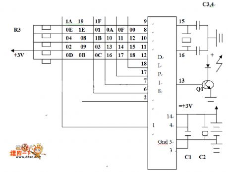
View full Circuit Diagram | Comments | Reading(587)
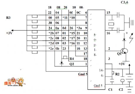
TV remote control 12 circuit
Published:2011/6/21 8:09:00 Author:John | Keyword: TV remote control
View full Circuit Diagram | Comments | Reading(581)
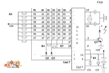
TV remote control 13 circuit
Published:2011/6/21 8:06:00 Author:John | Keyword: TV remote control

View full Circuit Diagram | Comments | Reading(717)
The AN7114 audio power amplifier circuit
Published:2011/6/20 21:27:00 Author:Seven | Keyword: power amplifier
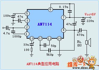
When Vvv=6.0V,THD=10% and RL=8Ω, the output power of AN7114 is 0.6W, the noise output is 3mV.Limit parameters: Vcc=11V, cooling power (without radiators) is 1.2W, which is 2.25W with radiators. The working temperature is -20—70℃, it is suitable for portable radios and stereo equipment as the power amplifier.
(View)
View full Circuit Diagram | Comments | Reading(1008)
The STK4101 application circuit
Published:2011/6/20 22:16:00 Author:Seven | Keyword: application circuit
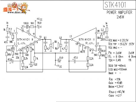
The STK4101 application circuit is shown in the above cirucit.
(View)
View full Circuit Diagram | Comments | Reading(1379)
The STK3042 application circuit
Published:2011/6/20 22:18:00 Author:Seven | Keyword: application circuit
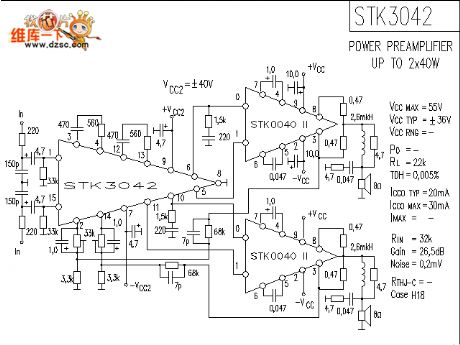
The STK3042 application circuit is shown as above.
(View)
View full Circuit Diagram | Comments | Reading(2728)
The Siemens S7-200PLC internal S485 connector circuit
Published:2011/6/20 22:18:00 Author:Seven | Keyword: Siemens, connector
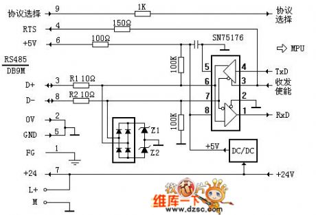
The Siemens S7-200PLC internal S485 connector circuit is shown as above.
(View)
View full Circuit Diagram | Comments | Reading(2381)
The STK1070 application circuit
Published:2011/6/20 22:19:00 Author:Seven | Keyword: application circuit
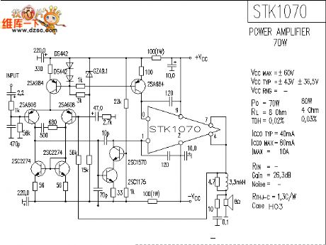
The STK1070 application circuit is shown as above.
(View)
View full Circuit Diagram | Comments | Reading(1333)
The STK4121 application circuit
Published:2011/6/20 1:47:00 Author:Seven | Keyword: application circuit
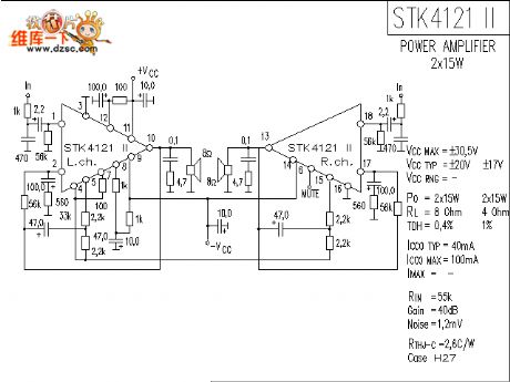
The STK4121 application circuit is shown in the figure.
(View)
View full Circuit Diagram | Comments | Reading(1288)
The STK4112 application circuit
Published:2011/6/20 22:12:00 Author:Seven | Keyword: application circuit
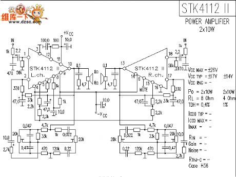
The STK4112 application circuit is shown as above.
(View)
View full Circuit Diagram | Comments | Reading(1779)
| Pages:196/250 At 20181182183184185186187188189190191192193194195196197198199200Under 20 |
Circuit Categories
power supply circuit
Amplifier Circuit
Basic Circuit
LED and Light Circuit
Sensor Circuit
Signal Processing
Electrical Equipment Circuit
Control Circuit
Remote Control Circuit
A/D-D/A Converter Circuit
Audio Circuit
Measuring and Test Circuit
Communication Circuit
Computer-Related Circuit
555 Circuit
Automotive Circuit
Repairing Circuit