
Index 180
The low humidity detecting circuit adoptted humicap CGS-H
Published:2011/7/10 2:28:00 Author:leo | Keyword: Low humidity, Detecting circuit
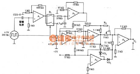
Picture 1 shows a circuit that uses the feature of low humidity of CGSH humicap to test other circuit. This circuit can even test other circuits with high accuracy under the atmosphere with less than 10% humidity. Operation amplifier A1, A2 and A3 are front amplifying circuit and difference amplifying circuit. The output signals of A1 pass through analog switch B1 and be alternately sent to A2 and A3 in order to eliminate the influence of change of temperature and the frequency noise and test steadily the output signals of sensor. A4,A5 and A6 are linear regulating circuit of sensor CGS-H and compensate the temperature by using the thermistor RL. (View)
View full Circuit Diagram | Comments | Reading(720)
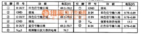
LM2468TA-The video final stage integrated circuit
Published:2011/7/10 2:30:00 Author:leo | Keyword: Video, Final stage, Integrated circuit
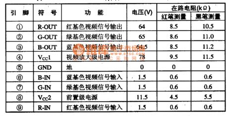
LM2468TA is a kind of video final stage integrated circuit made by America national semiconductor company. It is widely used in color screen of computer.
Inner circuit diagram. The integrated circuit LM2468TA has three fundamental color signal amplifier circuit and video intensifier stage power supplier circuit and so on. The inner circuit diagram of this integrated circuit is shown in the picture.
Pin function and dataThe integrated circuit LM2468TA uses 9 pin single-line package. The pin function and related data of integrated circuit are shown in the picture. (View)
View full Circuit Diagram | Comments | Reading(782)
LA4520-Single chip stereo player integrated circuit diagram
Published:2011/7/10 22:59:00 Author:leo | Keyword: Single chip, stereo player
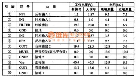
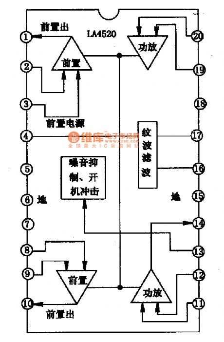
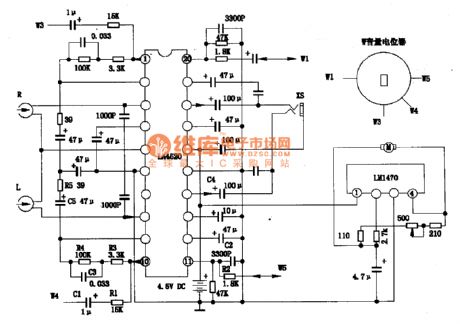
LA4520-Single chip stereo player integrated circuit diagram LA4520 is a single chip player integrated circuit. It is widely used in all kinds of players. LA4520 inner circuit diagram and pin functions:LA4520 inner circuit contains two similar playing fronted amplifier circuits, power amplifier circuits and so on. As picture 1 shows, this IC uses 20 pin dual line package and related information are shown in the picture. LA4520 classic applying circuit: the picture 2 shows its classic applying circuits.
(View)
View full Circuit Diagram | Comments | Reading(1779)
The FET chopping amplifier circuit
Published:2011/7/10 2:20:00 Author:leo | Keyword: The FET chopping amplifier circuit, AC amplifier
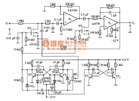
Picture 1 shows a FET chopping amplifier circuit. Chopping amplifier is made up of chopping part, AC amplifier, and modulator and so on. In this circuit, 3SK38A(VT1 and VT2) is specially developed for FET with grid-source light current and small capability . It is enhancement mode component with the maximum voltage value of 3V. The multivibrator made up of VT5 and VT6 generates square-wave signals which pass through the trigger formed by VT5 and VT6 to be reshaped. After reshaped, the signals are added to the grid of VT1 to be modulated and the modulating frequency is 185Hz. (View)
View full Circuit Diagram | Comments | Reading(1079)
LM2407T-Video output amplifier circuit
Published:2011/7/10 2:31:00 Author:leo | Keyword: Video, Output amplifier circuit
LM2407T is a type of video output amplifier circuit made by America national semiconductor company and is widely used in computer color screen.
1.Function features:The integrated circuit LM2407T contains three video output amplifier circuits, video output power supplying circuit, and other related circuits with same functions. 2.Pin functions and data:LM2407T adopts 11-pin single line package which you can check more from the picture. Other related data is also shown in the picture. (View)
View full Circuit Diagram | Comments | Reading(730)
LM2437T-The video output amplifier integrated circuit
Published:2011/7/10 2:31:00 Author:leo | Keyword: Video, Output amplifier, Integrated circuit
LM2437T is a kind of video output amplifier integrated circuit made by America national semiconductor company which is widely used in color screen of the computer.
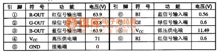
Function feature:The integrated circuit LM2437T contains R, G, B three fundamental color signal amplifier circuit, high voltage power supply circuit, low voltage power supply circuit and other related circuits.
Pin function and data:The integrated circuit LM2437T uses 9 pin single-line package which is widely used in color screen of Samsung 743DFS.The pin function and related data are shown in the picture. (View)
View full Circuit Diagram | Comments | Reading(852)
MPI System Launching Circuit Two of Soueast Lioncel
Published:2011/7/8 21:48:00 Author:Michel | Keyword: Soueast Lioncel, MPI System Launching, Circuit Two
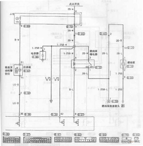
MPI System Launching Circuit of Soueast Lioncel (View)
View full Circuit Diagram | Comments | Reading(534)
Automatic Transmission Circuit Five of Soueast Lioncel
Published:2011/7/8 21:43:00 Author:Michel | Keyword: Soueast Lioncel, Automatic Transmission, Circuit Five
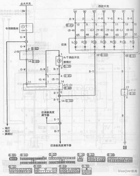
Automatic Transmission Circuit of Soueast Lioncel (View)
View full Circuit Diagram | Comments | Reading(504)
Automatic Transmission Circuit Seven of Southest Lioncel
Published:2011/7/8 21:34:00 Author:Michel | Keyword: Southest Lioncel , Automatic Transmission, Circuit Seven

Automatic Transmission Circuit of Southest Lioncel (View)
View full Circuit Diagram | Comments | Reading(505)
universal IF amplifier circuit
Published:2011/7/10 20:11:00 Author:John | Keyword: IF amplifier
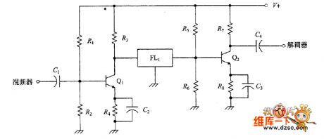
Crystal filters and mechanical filters all require specific coupling mechanism. The picture shows the coupling connection of the crystal filter which is between two bipolar transistors. Each level of the amplifier is a common emitter bipolar transistor amplifier. Bias voltage is set by the R1/R2 and R5/R6. And the connection to the filter circuit is direct, where the signal is not sensitive to the DC filter (thus this can not be called a mechanical filter). Figure shows another coupling connection, which is alternative both for mechanical filters and crystal filter.
(View)
View full Circuit Diagram | Comments | Reading(805)
MEMS stroboscopic drive circuit
Published:2011/7/1 5:39:00 Author:Fiona | Keyword: MEMS stroboscopic drive
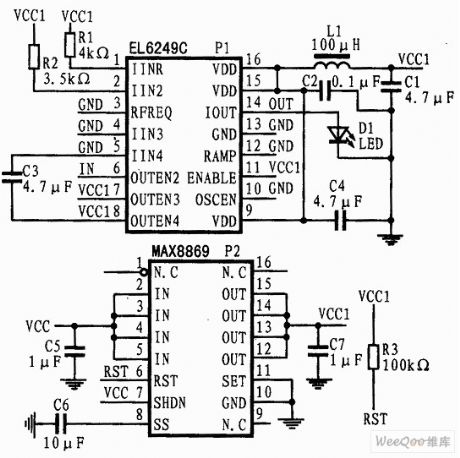
According tostroboscopic imaging principle,in order to collect the clear images of MEMS devices high-speed movement,this paper selects EL6249C as the drive chip to drive the high brightness laser diode to shine,and uses the narrow pulse signal with the same frequency as the function generator frequency and MEMS exercise frequency,meanwhile,it is used as the control signal for EL6249C,then sets the right external resistance to make EL6249C output appropriate electricity to drive LED to emit the required frequency light. The graph is the author of the design stroboscopic lighting circuit principle diagram. In this circuit, in order to ensure the required supply voltage is stable at 5V, the writer uses the MAX8869, so it can improve the accuracy and stability of the entire circuit.
(View)
View full Circuit Diagram | Comments | Reading(609)
New smart phone manager circuit
Published:2011/7/8 1:13:00 Author:Fiona | Keyword: New smart phone, manager
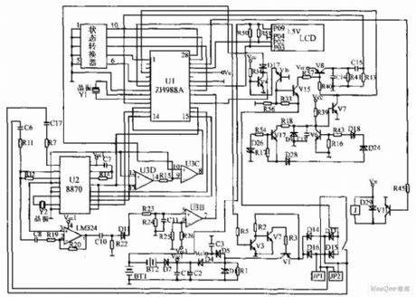
New smart phone manager circuit is shown as above,this device uses specific intelligent communications integrated controller chip ZH988A for the communications for the core to compose the smart phone manger, the circuit is shown as below. Its main functions are: 1 every phone can beset up19 users, the user has independent password and account, it achieves household management;2 limit each of user to do permissions, costs plan and so on; 3 open 110,119,114 and other free items; 4 automatically calculate the holding time and cost; 5 the data and passwords can be modified by keyboard;6 securitybeat monitoring;7 P / T is compatible and so on.
(View)
View full Circuit Diagram | Comments | Reading(1804)
interface circuit of power line carrier chip PM2300 and 89C2051
Published:2011/7/5 5:30:00 Author:Fiona | Keyword: power line carrier chip, interface
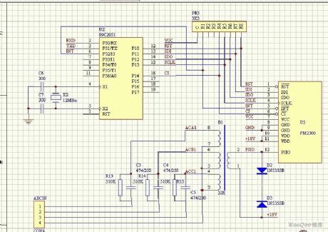
PM2300 is single power line carrier chip and 12 pin single in-line package thick-film integrated circuit for packaging the SSC P300 which is produced by Intellon company and analog circuit relative to power interface together.It has SPI synchronous serial interface.
(View)
View full Circuit Diagram | Comments | Reading(2076)
the interface circuit composed of RS232
Published:2011/7/5 5:30:00 Author:Fiona | Keyword: interface circuit

View full Circuit Diagram | Comments | Reading(684)
FT2232C and RS-422 conversion circuit
Published:2011/7/7 0:02:00 Author:Fiona | Keyword: conversion
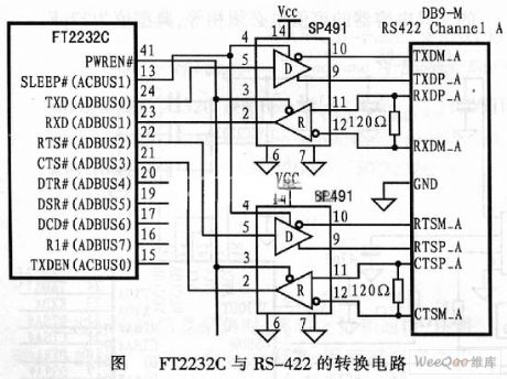
View full Circuit Diagram | Comments | Reading(744)
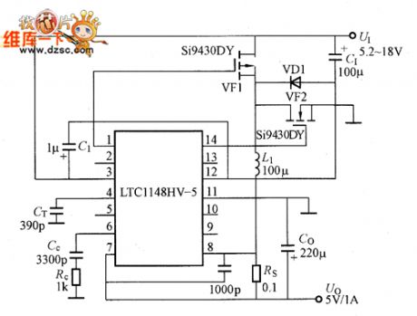
LTC1148 basic application circuit
Published:2011/7/8 6:13:00 Author:chopper | Keyword: basic, application circuit
View full Circuit Diagram | Comments | Reading(612)
pin configuration and the internal equivalent circuit of LTC1148
Published:2011/7/8 20:13:00 Author:chopper | Keyword: pin configuration, internal, equivalent circuit
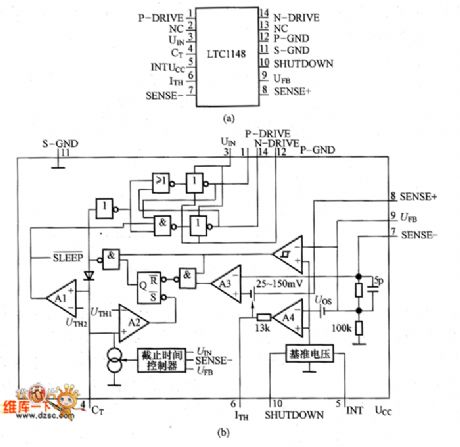
pin configuration and the internal equivalent circuit of LTC1148 are as shown in pictures. Pin ① (P-DRIVE) is connected to the grid of P-channel MOSFET,and when the output of this terminal is low, the high is the UI.When UI is lower than 8V,the external MOSFET sholuld use logic level threshold devices, and when UI is higher than 8V ,it should use the standard threshold devices.Pin ② (NC) is an empty pin, and it is connected to the power ground; Pin ③(UIN) is the power supply terminal.And 0.01 ~ 0.1μF ceramic bypass capacitor should be connected between pin ③ and pin @.
(View)
View full Circuit Diagram | Comments | Reading(576)
LTC1147 basic application circuit
Published:2011/7/8 20:22:00 Author:chopper | Keyword: basic, application
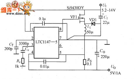
LTC1147 basic application circuit is shown as picture,and the input supply voltage is 5.2~14V, the output is 5V/1A.If the basic work method adoptscontinuous current mode, the MOSFET will repeat on/off,and flow through the current intermittently.This current is outputafter the smoothness of L1 and Co.Therefore, when the efficiency is 100%,the area during the conduction period of input voltage and the MOSFET is equal to the area within a period that MOSFET repeats on/off.
(View)
View full Circuit Diagram | Comments | Reading(511)
pin configuration and the internal equivalent circuit of LTC1147
Published:2011/7/8 20:31:00 Author:chopper | Keyword: pin configuration, internal, equivalent circuit
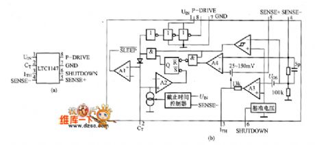
LTC1147 is mainly used for power supply circuits like DC - DC converter power of laptops and handheld computers,and also for the portable measuring instruments,battery-powered digital device,mobile phone,DC distribution system,GPS system.It has output voltages of 3.3V and 5V specifications,and can be selected based on the power supply voltage of main circuit of application system.In addition,the external P-channel MOSFET and N-channel MOSFET can expand output current,and can use LTC1148 whose efficiency is higher than LTC1147 or LTC1149/LTC1159 whose maximum input voltage is up to 48V.Thus,it can constitute a power supply circuit of high efficiency, high output current.
(View)
View full Circuit Diagram | Comments | Reading(670)
basic application circuit of YDS-100T series DC-DC converter
Published:2011/7/8 20:33:00 Author:chopper | Keyword: basic application , DC-DC converter
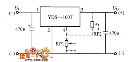
basic application circuit of YDS-100T series DC-DC converter is shown as picture
(View)
View full Circuit Diagram | Comments | Reading(574)
| Pages:180/250 At 20161162163164165166167168169170171172173174175176177178179180Under 20 |
Circuit Categories
power supply circuit
Amplifier Circuit
Basic Circuit
LED and Light Circuit
Sensor Circuit
Signal Processing
Electrical Equipment Circuit
Control Circuit
Remote Control Circuit
A/D-D/A Converter Circuit
Audio Circuit
Measuring and Test Circuit
Communication Circuit
Computer-Related Circuit
555 Circuit
Automotive Circuit
Repairing Circuit