
Index 169
MAGNETIC_PICKUP_PHONO_AMPLIFIER
Published:2009/6/15 23:07:00 Author:May
This preamp is RAA compensated for use with magnetic phone cartridges. (View)
View full Circuit Diagram | Comments | Reading(1880)
JFET_HEADPHONE_AMPLIFIER
Published:2009/6/15 23:03:00 Author:May
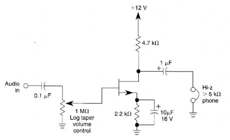
This circuit can drive high-impedance headphones from a low impedance low-level source. Gain is about 5X to 10X depending on headphone irnpedance. A volume control is included. (View)
View full Circuit Diagram | Comments | Reading(1490)
AUDIO_AMPLIFIER_WITH_TUNEABLE_FILTER
Published:2009/6/15 23:00:00 Author:May
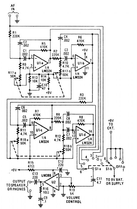
This audio amplifier can tune from 500 to 1500 Hz and will drive a speaker or headphones. Use-ful for CW reception or other receiver applications, only two IC devices are needed. (View)
View full Circuit Diagram | Comments | Reading(766)
MINI_AMPLIFIER_USING_LM1895N
Published:2009/6/15 22:58:00 Author:May
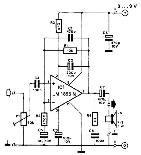
With 3-V to 9-V supplies, this amplifier can provide from 100-mW to 1-W output into a 4 Ω and bandwidth is approximately 20 kHz @ 3 dB.This circuit is useful for low-power and battery applications. Drain is 80 mA @ 3 V or 270 mA @ 9 V at maximum signal conditions. (View)
View full Circuit Diagram | Comments | Reading(752)
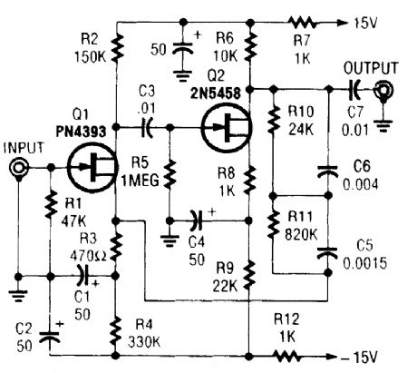
CONSTANT_VOLUME_AMPLIFIER
Published:2009/6/15 22:57:00 Author:May
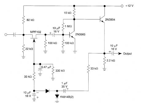
The amplifier has an output level that shifts about 6 dB for a 40-dB input variation. (View)
View full Circuit Diagram | Comments | Reading(803)
HEADPHONE_AMPLIFIER
Published:2009/6/15 22:48:00 Author:May
Built around Precision Monolithics Inc. OP-50 op amps,this amplifier will drive 100-Ω to 1-kΩ headphone,is flat within 0.4 dB from 10 Hz to 20 kHz,and has a THD of less than 0.01% over most of the audio range. Amplification factor is about 6X. (View)
View full Circuit Diagram | Comments | Reading(2520)
FAST_HIGH_VOLTAGE_LINEAR_POWER_AMP
Published:2009/6/15 22:32:00 Author:May
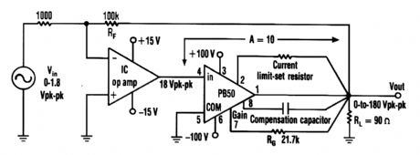
An Apex PB50 Booster Amplifier,plus an IC op amp,can be used In a high-voltage op amp thatconverts a small analog signal to a 180-V p-p signal. (View)
View full Circuit Diagram | Comments | Reading(872)
AUDIO_POWER_AMPLIFIER
Published:2009/6/15 22:31:00 Author:May
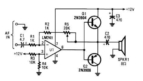
The circuit, built around an LM741 op amp configured as an inverting amplifier, is used to drive complementary transistors (Q1 and Q2). The op amp's feedback loop includes the base-emitter junctions of both transistors-an arrangement that helps to reduce crossover distortion that would normally occur as a result of the emitter-to-base junction voltage drop of about 0.6 V. Potentiometer R5 varies the amplifier's voltage gain from 1 to about 20. As much as 0.5 TV can be obtained from the circuit if a heatsink is added to the transistors. (View)
View full Circuit Diagram | Comments | Reading(9581)
SUBWOOFER_CROSSOVER_AMPLIFIER
Published:2009/6/15 22:26:00 Author:May
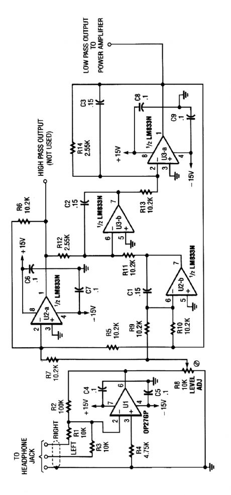
The electronic-crossover circuit contains a summing ampplifier that combines the left that combines the left and right channels from a stereo's headphone jack. Originally used in a subwoofer system, the above circuit might be useful in similar audio applications. (View)
View full Circuit Diagram | Comments | Reading(1377)
18_W_BRIDGE_AUDIO_AMPLIFIER
Published:2009/6/15 22:18:00 Author:May
Two LM383 IC devices are used in a bridge circuit that is useful for auto sound applications. (View)
View full Circuit Diagram | Comments | Reading(1931)
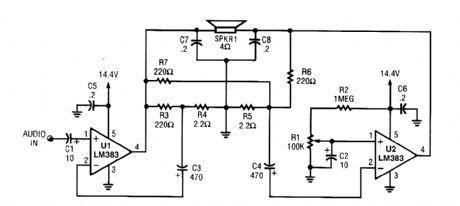
SUBWOOFER_AMPLIFIER
Published:2009/6/15 22:17:00 Author:May
Designed to feed a low-frequency subwoofer speaker system,the amplifier is capable of up to 100 W into an 8-Ω load. The OPA541BM op amp requires heatsinkins and is manufactured by Burr-Brown Corporation. A damping control and a relay to eliminate turn-on and turn-off thump in the speaker is included. (View)
View full Circuit Diagram | Comments | Reading(2005)
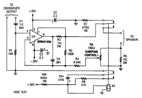
LM38O_PERSONAL_STEREO_AMPLIFIER
Published:2009/6/15 22:05:00 Author:May
With the simple circuit, you can use your personal stereo to drive standard 8-Ω speakers. (View)
View full Circuit Diagram | Comments | Reading(809)
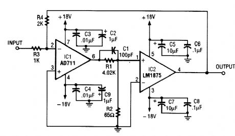
10_W_INVERTING_COMPOSITE_AMPLIFIER
Published:2009/6/15 22:04:00 Author:May
Using an LM1875,a 10-W amplifier can bebuild using just two IC devices The gam=R4/R3. Note that IC12 must be heatsinked (View)
View full Circuit Diagram | Comments | Reading(1428)
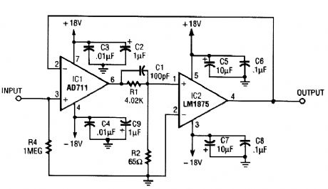
10_W_NONINVERTING_COMPOSITE_AMPLIFIER
Published:2009/6/15 22:03:00 Author:May
By using an LM1875, suitably heatsinked, a 10-W amplifier that uses two IC devices can be built, IC2 must be heatsinked. (View)
View full Circuit Diagram | Comments | Reading(1490)
MOSFET_POWER_AMPLIFIER
Published:2009/6/15 22:02:00 Author:May
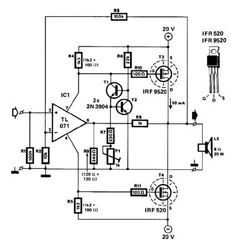
Two complementary MOSFETs are used to deliver 20 W into 8 Ω. A TL071 op amp is used as an input amplifier. The MOSFETs should be heatsinked with a heatsink of better than 5℃/W capability. THD is less than 0.15% from 100 Hz to 10 kHz. (View)
View full Circuit Diagram | Comments | Reading(3512)
A_33_W_BRIDGE_COMPOSITE_AMPLIFIER
Published:2009/6/15 21:56:00 Author:May
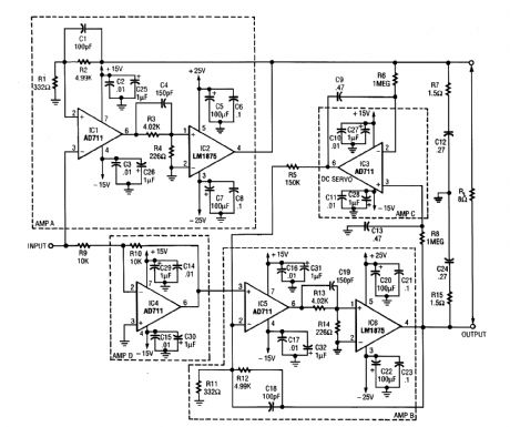
Two LM1875 ICs provide 33 W of audio. IC4 is used as a phase inverter. IC6 and IC2 must be heatsinked. (View)
View full Circuit Diagram | Comments | Reading(1011)
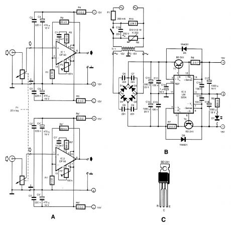
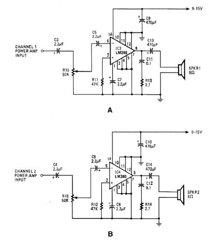
DUAL_AUDIO_AMPLIFIER
Published:2009/6/15 21:53:00 Author:May
View full Circuit Diagram | Comments | Reading(889)
HALF_WATT_SINGLE_CHANNEL_AUDIO_AMPLIFIER
Published:2009/6/15 21:31:00 Author:May
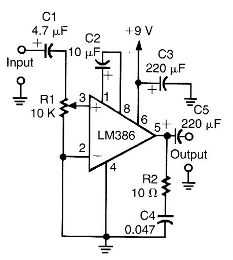
This circuit uses an LM386 IC and will work from 6- to 12-V battery sources. Output is about 0.5 W into 8 Ω. (View)
View full Circuit Diagram | Comments | Reading(850)
40_W_AMPLIFIER
Published:2009/6/15 21:30:00 Author:May
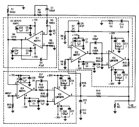
This circuit uses two LM1875 devices and a dc servo loop. This circuit provides 40-W output. IC3 and IC5 must be heatsinked. (View)
View full Circuit Diagram | Comments | Reading(1056)
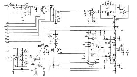
20_W___20_W_STEREO_AMPLIFIER
Published:2009/6/15 21:26:00 Author:May
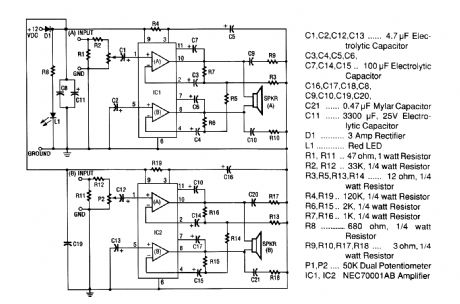
The 20-W + 20-W stereo amp consists of two complete, separate 20-W RMS bridge-type ampli-fiers. The input signal source is brought into the amplifier through the voltage divider network, which is made up of R1, R2, and P1. Resistor R1 provides a load impedance between the signal source and ground. Resistor R2 couples that signal to potentiometer P1.The signal is coupled by capacitor C1 to the noninverting (+) input (pin 1) of intemal amplifier (A) of IC1, where the signal is greatly amplified. Capacitor C2 couples the (+) input of the other (B) internal amplifier of IC1 to ground. That causes the input signal, which is referenced to ground, to be coupled to both amplifiers because both the inputs and outputs of IC 1 (A) and IC 1 (B) are connected in a bridge configuration. Notice that the output of IC1 (A) from pin 10 is connected to one side of the speaker and the output of IC1 (B) from pin 8 is connected to the other side of the speaker. That is why the speakers used cannot have one side connected to ground. Resistors R6 and R7 set the gain of the amplifier. Resistors R9 and R10 and capacitors C9 and C10 provide frequency stability ancl pre-vent oscillation. Capacitors C6 and C7 provide bootstrapping, which prevents distortion at low fre-quencies. LED L1 lights up by way of a series resistor connected from the anode to +12 Vdc when power is applied.Power for both IC1 and IC2 is brought in through D1 (to protect amplifiers from reverse polar-ity). Capacitor C11 provides additional power supply line filtering. This booster is capable of pro-ducing 20 W RMS output out of each channel. (View)
View full Circuit Diagram | Comments | Reading(764)
| Pages:169/250 At 20161162163164165166167168169170171172173174175176177178179180Under 20 |
Circuit Categories
power supply circuit
Amplifier Circuit
Basic Circuit
LED and Light Circuit
Sensor Circuit
Signal Processing
Electrical Equipment Circuit
Control Circuit
Remote Control Circuit
A/D-D/A Converter Circuit
Audio Circuit
Measuring and Test Circuit
Communication Circuit
Computer-Related Circuit
555 Circuit
Automotive Circuit
Repairing Circuit