
Index 176
Gain Programmable Amplification Circuit By Using Concatenate Stages
Published:2011/7/19 9:15:00 Author:Robert | Keyword: Gain, Programmable, Amplification, Concatenate, Stages
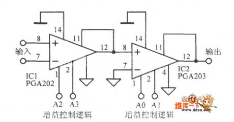
The picture shows the gain programmable amplification circuit by using concatenate stages. (View)
View full Circuit Diagram | Comments | Reading(495)
16dB Wideband Video Amplification Circuit
Published:2011/7/18 10:06:00 Author:Robert | Keyword: 16dB, Wideband, Video, Amplification
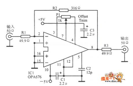
The picture shows the 16dB wideband video amplification circuit. (View)
View full Circuit Diagram | Comments | Reading(504)
Practical 400MHz Differential Amplification Circuit
Published:2011/7/18 10:04:00 Author:Robert | Keyword: Practical, 400MHz, Differential, Amplification
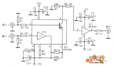
The picture shows the practical 400MHz differential amplification circuit. (View)
View full Circuit Diagram | Comments | Reading(721)
Durable Television Signal Conversion Amplification Principle Circuit
Published:2011/7/18 10:30:00 Author:Robert | Keyword: Durable, Television, Signal, Conversion, Amplification, Principle

The picture shows the durable television signal conversion amplification principle circuit. (View)
View full Circuit Diagram | Comments | Reading(751)
C51 Single-Chip Microcomputer Serial Communication Hardware Circuit
Published:2011/7/15 1:58:00 Author:Joyce | Keyword: C51 Singlechip, Serial Communication , Hardware
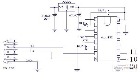
The full-duplex serial communication mouth of 51 SCM makes it convenient to have serial communication between a single chip microcomputer and a computer .But there’s some requirements for serial communication , such as serial port of the computer should be RS232 level ,while that of the SCM is TTL level; a level conversion circuit is needed between them. Here we use a dedicated chip MAX232 for conversion. A few triodes can be used to conduct simulated conversion as well, but it is more simple and reliable to use dedicated chips. We connect the serial ports in three-wire system.
(View)
View full Circuit Diagram | Comments | Reading(962)
AN360—the low noise audio preamplifier integrated circuit
Published:2011/7/15 19:38:00 Author:Borg | Keyword: audio preamplifier, integrated circuit
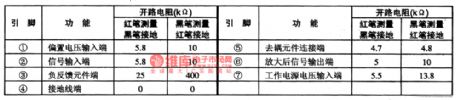
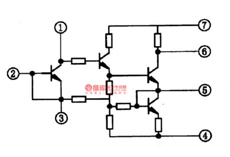
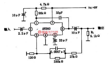
AN360 is a low-noise audio preamplifier integrated circuit produced by Panasonic, which is used in domestic stereo systems as the audio preamplifier.1. the internal circuit and pin functions of AN360AN360 consists of 3 stages of amplifiers, and voltage gain of its open loop equivalent circuit is high, the 1st loading resistor can be connected externally, a proper amplifier can be chosen. The IC is in 7-pin single in-line package, whose internal equivalent circuit is shown in figure 1-10, and pin functions and data are listed in table 1.
(View)
View full Circuit Diagram | Comments | Reading(3534)
The FM intermediate frequency amplifier integrated circuit
Published:2011/7/15 20:45:00 Author:Borg | Keyword: intermediate frequency amplifier, integrated circuit
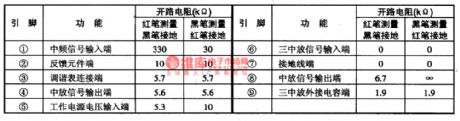
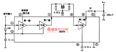
AN278 is a FM intermediate frequency amplifier integrated circuit produced by Panasonic, which is used in domestic stereos and FM radios as the FM intermediate frequency amplifier.1. the internal circuit and pin functions of AN278The features of AN278 are that the LEV fault of the internal amplitude limiter is low, the symmetry is good; the 2nd and 3rd is coupled directly, and they can also connected with pottery filter: when the PLL circuit is working, the limiter can offer enough LEV; it can be connected with the tune indicating circuit, etc. AN278 is in single 9-pin in-line package.
(View)
View full Circuit Diagram | Comments | Reading(1300)
The MOSFET drive circuit
Published:2011/7/17 22:33:00 Author:Borg | Keyword: MOSFET drive
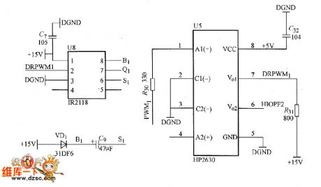
The drive core is MOSFET specialized drive core IR2118 which is produced by IR Corp., it is a single line drive; the photoelectric clutch, which can separate the electricity from light and improve the voltage function, is the HP2630 which is produced by HP Corp. The PWM output by DSP is driving IR2118 after it is separated by the photoelectric coupler HP2630, and then the signal output by IR2118 is driving MOSFET. Notes: only when the voltage is over 9.5V, does IR2118 regard it as the high LEV, or it is the low LEV, the circuit is shown in the figure.
(View)
View full Circuit Diagram | Comments | Reading(1281)
SN822lP FSK Call Screening Decoding Intergrated Circuit
Published:2011/7/15 2:55:00 Author:Michel | Keyword: FSK Call Screening, Decoding Intergrated Circuit
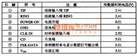
SN8221P is a call screening decoding integrated circuit that is widely used in all kinds of call screening communication devices.
One Functions and FeaturesSN8221P integrated circuit contains frequency shift keying callscreening data signal processing circuit, clocking oscillation signal processing circuit, the power switch control circuit, piece choosing circuit, call screen pretreatment and identify circuit, the power supply circuit and some other auxiliary functions circuit.
Two Pins Functions and DataSN8221P integrated circuit uses dual in-line package which is widely used in wireless telephones of TCL beauty the voice series and its pins functions and data are shown as table 1.
Table 1:Pin Functions and Data (View)
View full Circuit Diagram | Comments | Reading(627)
NICAM Solution Decoding Intergrated Circuit
Published:2011/7/15 5:34:00 Author:Michel | Keyword: Decoding Intergrated Circuit
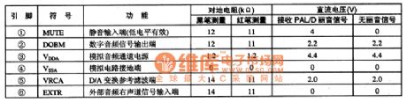
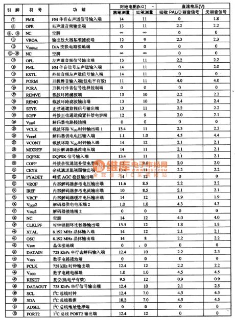
SAA7283ZP is nicam solution decoding intergrated circuit and it is used as nicam solution
decoding in kinds of domestic and imported big screen color TVs.
SAA7283ZP contains all functions that nicam solution decoder needs and it includes 8.192 MHz clock circuit, the I2C bus interface circuit, mute control circuit, carrier loop and some other auxiliary functions circuit. The IC uses 52 feet dual in-line package and its pins functions and the data measured from KONKA T3888N large screen color TV are shown as the table 1.The voltage of (49) and (50) feet change a little when they are measured.
Table 1:Pins Functions of5M72832P and Measuring Data of KONKA T3888N Color TV (View)
View full Circuit Diagram | Comments | Reading(708)
The power MOSFET grid drive circuit
Published:2011/7/17 22:47:00 Author:Borg | Keyword: power MOSFET, grid drive
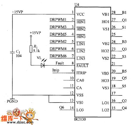
The power MOSFET grid drive circuit is the 6-line integrated IC drive core IR2130 produced by IR Corp. In the IC, there are the over-current/voltage and low voltage protection, lock and indication circuit, so the users can conveniently use it to protect the power MOSFET under drive. IR2130 controls the 3 power tubes with the internal bootstrap technique. In the real system, the bootstrap capacitor reacts slowly, the system separator DC-DC provides with power for the circuit on the bridge arm power MOSFET.
(View)
View full Circuit Diagram | Comments | Reading(2129)
The power drive circuit
Published:2011/7/17 22:36:00 Author:Borg | Keyword: power drive circuit
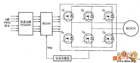
The power drive circuit is shown as above.
(View)
View full Circuit Diagram | Comments | Reading(783)
The serial communication connector circuit of TMS320F2812
Published:2011/7/17 22:35:00 Author:Borg | Keyword: serial, communication connector
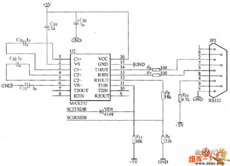
The serial communication connector circuit of TMS320F2812 is shown as above.
(View)
View full Circuit Diagram | Comments | Reading(1603)
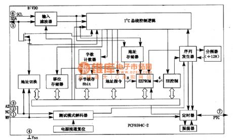
PCF8594C-2-E2ROM Storage Integrated Circuit
Published:2011/7/16 10:39:00 Author:Michel | Keyword: Storage Integrated Circuit
(View)
View full Circuit Diagram | Comments | Reading(643)
zeropassage examination phase shifting trigger drive circuit
Published:2011/7/17 7:27:00 Author:Fiona | Keyword: zeropassage examination, phase shifting
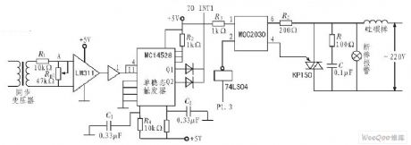
Zeropassage examination phase shifting trigger drive circuit is shown as above: (View)
View full Circuit Diagram | Comments | Reading(849)
The circuit using NPN tube and voltage-regulator tube to realize the control of constant voltage and constant current
Published:2011/7/16 6:16:00 Author:Fiona | Keyword: NPN tube and voltage-regulator tube, the control of constant voltage and constant current
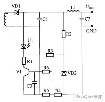

The circuit using NPN tube and voltage-regulator tube to realize the control of constant voltage and constant current is shown as above:
(View)
View full Circuit Diagram | Comments | Reading(913)
control of constant voltage and constant current circuit composed of PNP tube and voltage-regulator tube
Published:2011/7/16 6:19:00 Author:Fiona | Keyword: control of constant voltage and constant, PNP tube and voltage-regulator tube
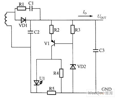
control of constant voltage and constant current circuit composed of PNP tube and voltage-regulator tube is shown as above:
(View)
View full Circuit Diagram | Comments | Reading(1069)
Control of constant voltage and constant current circuit composed of current amplifier
Published:2011/7/18 2:51:00 Author:Fiona | Keyword: current amplifier, constant voltage and constant current
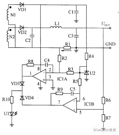
Constantvoltage circuit working principle:U2,ICIB,R6,R7,VD4,R10 and U1 form the voltage control loop. U2 (TL431) is a precision voltage regulator, cathode K and the control electrode R directly shorts circuit to form the precision 2.5V reference voltage. R4 is U2's current-limiting resistor.2.5V reference voltage is sent to the inverting input ICIB (6 pin) by the resistor R5; and non-inverting input (5 pin) is set by R6, R7's partial pressure ratio.If the output voltage rises,the UR7's voltage rises too,this voltage compares to the negative terminal 2.5V reference voltage,7-pin outputs error signal,and then becomes into a current signal through the VD4 and RIO,inflows the optocoupler's LED, and then through the feedback control and network control to make the primary side PWM output duty cycle,so that the output voltage is in the constant state.
(View)
View full Circuit Diagram | Comments | Reading(3024)
Class B Amplification Complementary Symmetry Working Principle Circuit
Published:2011/7/15 19:51:00 Author:Robert | Keyword: Class B, Amplification, Complementary, Symmetry, Working, Principle
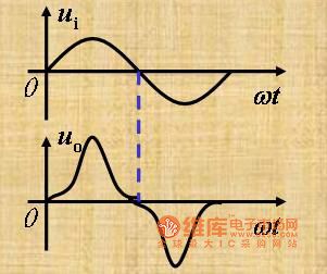
The picture shows the class B amplification complementary symmetry working principle circuit.
(1)Its working principle.
Static: IB=0, IC=0, uo=0
Dynamic:
When it is in the ui's positive half cycle, the NPN transistor is in the mode of amplification and the PNP transistor is cloced. The current through RL is iC1.
When it is in the ui's negative half cycle, the PNP transistor is in the mode of amplification and the NPN transistor is cloced. The current through RL is iC2. (View)
View full Circuit Diagram | Comments | Reading(743)
TDA2003 Power Amplifier Circuit
Published:2011/7/15 20:13:00 Author:Robert | Keyword: Power, Amplifier
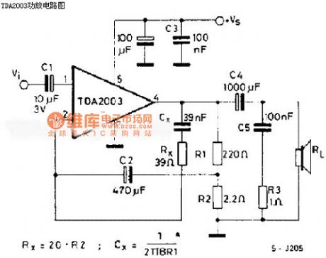
The picture shows the TDA2003 power amplifier circuit. (View)
View full Circuit Diagram | Comments | Reading(1170)
| Pages:176/250 At 20161162163164165166167168169170171172173174175176177178179180Under 20 |
Circuit Categories
power supply circuit
Amplifier Circuit
Basic Circuit
LED and Light Circuit
Sensor Circuit
Signal Processing
Electrical Equipment Circuit
Control Circuit
Remote Control Circuit
A/D-D/A Converter Circuit
Audio Circuit
Measuring and Test Circuit
Communication Circuit
Computer-Related Circuit
555 Circuit
Automotive Circuit
Repairing Circuit