
Index 174
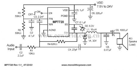
A digital power amplifier circuit
Published:2011/7/22 1:24:00 Author:Ecco | Keyword: digital power amplifier
View full Circuit Diagram | Comments | Reading(1059)
Practical Circuit of Frequency Counter
Published:2011/7/19 11:24:00 Author:Michel | Keyword: Frequency Counter, Practical Circuit
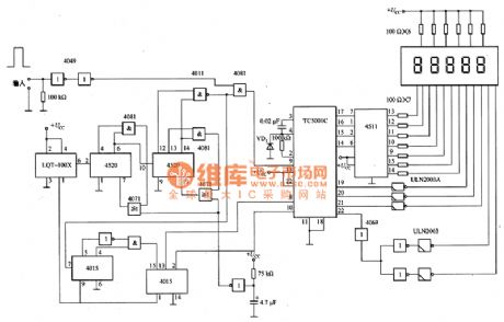
The picture 1 is practical circuit of frequency counter.Frequency measurement range is from 10kHz to several Hz.In the circuit,the first indication is fixed as 0, measurement period is 1.2 s and measuring time is 1 s. LQT-lOOX is the market crystals module. The circuit can be used as revolution meter and it is on the measured rotary actuator.For example,on the motor shaft every turn installs 6 pulse encoders ,which can directly read motor speed of every 1 min,namely the digital revolution indicator.
If the amplifier circuit is added to the input portion ,the input signal is properly amplified and detecting the dc motor pulse current situation and the speed of the motor are also available.
(View)
View full Circuit Diagram | Comments | Reading(2425)
Time to Acousto-optic Reminding Circuit
Published:2011/7/19 11:22:00 Author:Michel | Keyword: Time, Acousto-opticReminding Circuit
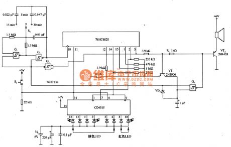
Picutre 1 is time to acousto-optic reminding circuit.In the circuit,74 HC4020 is 14 counter; CD4015 is eight shift register and S2 is reduction switch.When it instantly closes, 74 HC4020 and CD4O15 also reset and the G1 and C2 may constitute a time interval oscillator. S1 is selected switch and it can choose 5 min, 15 min and 30 min.The cirucit gives sound and light alarm signal when time is up.
Picture 1:Time to Acousto-optic Reminding Circuit (View)
View full Circuit Diagram | Comments | Reading(809)
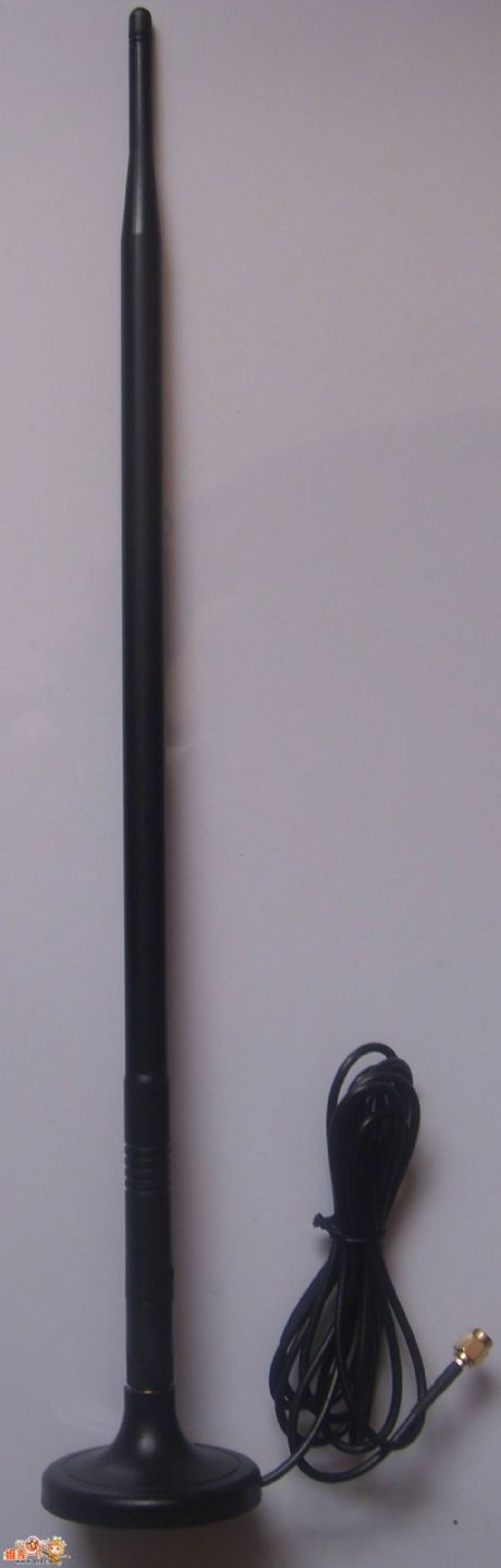
2.4G High-gain Aerial ,WIFI Aerial
Published:2011/7/14 0:20:00 Author:Joyce | Keyword: 2.4G, High-gain, Aerial, WIFI, Aerial
(View)
View full Circuit Diagram | Comments | Reading(984)
Two-path Video Amplifier Circuit Composed of MAX457
Published:2011/7/14 0:33:00 Author:Joyce | Keyword: Two-path, Video, Amplifier
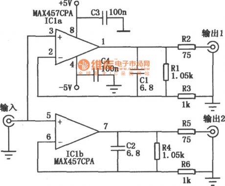
As shown in the figure is the high performance video distributor/amplifier circuit composed of MAX457. MAX457 has two units of video amplifier with stable gains,which could drive 75Ω load directly and its - 3dB bandwidth is not less than 70MHz. Its characteristic is small input capacitance (the typical value is 4pF), 100μA input bias current,high isolation between two amplifiers ( the typical value in 5MHz frequency point is 72dB).
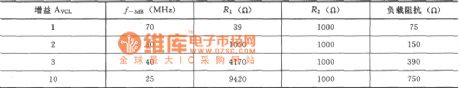
Changing resistance R1, R2,R4, R5, would alter the output impedance of the amplifier circuit as well ,with the specific data shown as follows. (View)
View full Circuit Diagram | Comments | Reading(1142)
The amplifer circuit diagram formed by LM118 and used in device
Published:2011/7/16 2:49:00 Author:leo | Keyword: Instrument amplifer
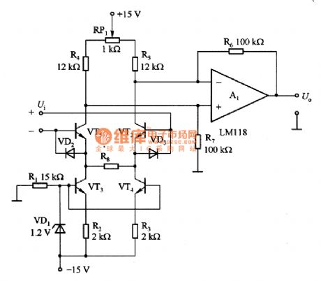
Picture 1 is an instrument amplifier. It is made up of LM118 and others. In this circuit, VT1 and VT2 can form surface input circuit. They can form constant flow source which can supply steady current for differential amplifier A1;VD1 can supply base voltage(1.2V) with zero degree temperature factor to constant flow source. In order to make the input circuit have a good linearity working state, The output current of VT3 and VT4 should be double ofthe current passing through it when being added differential voltage.If needing smaller input current, all resistances should be increased by 100 times and replace LM118 with LM318. (View)
View full Circuit Diagram | Comments | Reading(974)
A differential value detecting circuit made by LTC1043
Published:2011/7/16 2:50:00 Author:leo | Keyword: Detecting circuit, differential value
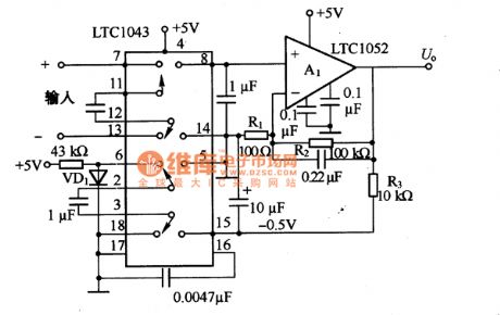
As the picture a and b show, this is a differential value detecting circuit made by LTC1043, in which the differential terminal is changed into single terminal output terminal. Picture20 (a) shows the basic detecting amplifier with speeding up capacitor mode. The sample C1 is connected to differential input signal terminal and uses differential input voltage Ui to charge. And LTC1043 is used to handoff and connect C1 to C2 while the electric charge of C1 is transferred to Q. Due to the repeating frequency of hundreds to some dozens of thousands, voltage of the differential input signals changes to signal input voltage of A1. The repeating frequency is decided by LTC1043 and capacity of C3(EXT capacitor ). (View)
View full Circuit Diagram | Comments | Reading(1157)
ULN3814A-The sinle chip audio integrated circuit
Published:2011/7/16 2:53:00 Author:leo | Keyword: Sinle chip, Audio, Integrated circuit
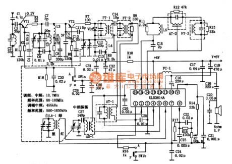
ULN3814A is a kind of integrated circuit used in pocket-sized radio and other kinds of radios.
1.ULN3814A integrated chip inner circuit diagram and pin functions:ULN3814A contains amplitude-modulated oscillator, frequency mixing circuit, frequency-modulating circuit, AGC, AFC, and audio power amplifier as well as voltage-stabilizing circuit.
2.Main parameters of ULN3814A:(1)No-working voltage coverage is from 3 V to 1 V and working voltage coverage is 6 V and 9 V. (2)Output power. Under the condition that Vcc is 7\6 V and R(L) is 8 ohms, the output power is 0.35W. When Vcc is 9 V and R(L) is 8 ohms, the output power is 0.6W.(3)Voltage gain and input resistance. When the voltage gain of the power amplifier is over 40 dB, input resistance is 200kohms. (View)
View full Circuit Diagram | Comments | Reading(902)
LM4766-Hi-Fi stereo amplifier integrated circuit
Published:2011/7/16 2:53:00 Author:leo | Keyword: Stereo amplifier, Integrated circuit
LM4766 is a high-quality stereo amplifier integrated circuit which is a hot Hi-Fi amplifier.
1.LM4766 inner circuit diagram:LM4766 inner circuit has the same function with the amplifier outer circuit. Besides, the inner circuit also contains other protecting circuits. When the voltage is over the maximum value, the circuit will be cutoff automatically. When the load is over the set maximum value or temperature is over 165 oC, the circuit will be closed automatically. The circuit is shown in the picture.
2.LM4766 main parameters:LM4766 has an operating source voltage of 士10 to 土30V. The maximum value of power sources is 土37V. The constant output power average is 40 W with 8 n load.
3.LM4766 classic applying circuit:The classic applying circuit is show in the picture. (View)
View full Circuit Diagram | Comments | Reading(1220)
TPA2OOOD2 No filter D type audio power amplifier integrated circuit
Published:2011/7/16 2:55:00 Author:leo | Keyword: No filter, D type, Audio power amplifier, Integrated circuit
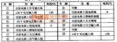
TPA2OOOD2 is a kind of new D type audio power amplifier integrated circuit. It does not need a filter port and beproduced by Texas Instrument Company in America. It is applied to multimedia speaker system of USB drive, portable type DVD player, PDAS and notebook. Besides, it can also be used in audio player with 2 W output power.
TPA2OOOD2 Function Features:The integrated circuit TPA2OOOD2 overcomes the shortcoming of the original D type audio player that needs a big LC filter. It can not only offer high efficiency to D type power amplifier but also reduct the volume of IC components.
(View)
View full Circuit Diagram | Comments | Reading(1336)
LBl0427A-Communication single chip microcomputer integrated circuit
Published:2011/7/16 2:55:00 Author:leo | Keyword: Communication, single chip, microcomputer, integrated circuit
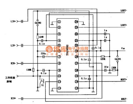
LBl0427A is a kind of communication single chip microcomputer integrated circuit which is widely used in caller ID telephone.
Function features:The integrated circuit LBl0427A contains impulse/duel-frequency signal generator, LCD display drive circuit, FSK/DTMF caller ID decoding circuit, keyboard order coding circuit, hands-free trigger circuit, power resources testing circuit, key sound drive circuit and so on.
Pin functions and data:LBl0427A uses 80 pin package. The pin functions and related data are shown in the picture. (View)
View full Circuit Diagram | Comments | Reading(783)
CXAl279AS analog control integrated circuit
Published:2011/7/16 2:55:00 Author:leo | Keyword: Balance control, stereo system
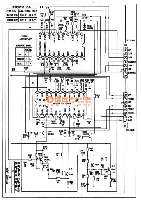
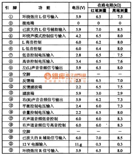
CXAl279AS is a volume, bass, treble, balance control, and mix control integrated circuit produced by Sony Company in Japan, which is widely used in television stereo system and other stereo systems. 1.CXAl279AS classic applying circuitCXAl279AS is usually used with μPCl89lACY to carry out the processing of surround sound signals. Its classic applying circuit is shown in the picture 1.2.CXAl279AS pin functions and data3.Circuit working process(1)Bass/treble/balance control (2)Volume control (View)
View full Circuit Diagram | Comments | Reading(1164)
The Digital programmable amplifier circuit
Published:2011/7/11 2:24:00 Author:TaoXi | Keyword: Digital, programmable amplifier
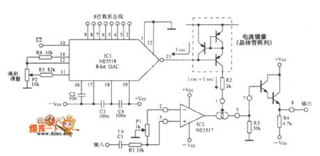
The Digital programmable amplifier circuit is as shown in figure:
(View)
View full Circuit Diagram | Comments | Reading(737)
The Wide dynamic range gain control amplifier circuit
Published:2011/7/11 2:25:00 Author:TaoXi | Keyword: Wide dynamic range, gain control, amplifier circuit
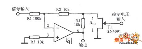
The Wide dynamic range gain control amplifier circuit is as shown in the figure:
(View)
View full Circuit Diagram | Comments | Reading(769)
Automatic gain control amplifier circuit diagram
Published:2011/7/21 1:23:00 Author:Ecco | Keyword: Automatic , gain control amplifier
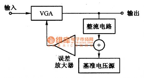
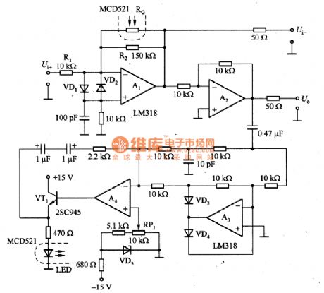
Figure 1 is automatic gain control amplifier. Figure 1 (a) is the block diagram of automatic gain control amplifier which is composed of the variable gain amplifier VGA, rectifier circuit, reference voltage source and error amplifier. Figure 1 (b) is the actual circuit, A1 may constitute VGA amplifier, of which the gain depends on the ratio of resistance value, that is the RG of the optical coupler, and the maximum gain is 15 times which is decided by the ratio of R2 and R1, and the minimum gain is determined by the minimum value of RG.
(View)
View full Circuit Diagram | Comments | Reading(3530)
Transistor audio power amplifier circuit diagram
Published:2011/7/21 2:24:00 Author:Ecco | Keyword: Transistor , audio power amplifier
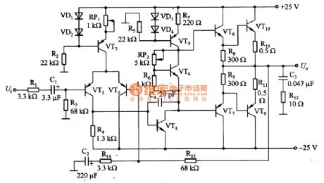
Figure 1 shows the transistor audio amplifier circuit. Flat frequency characteristics of the circuit is 2Hz to 200kHz, and the distortion is below 0.2% at lkHz (30W), and the output power is 30W. VT3 and VT5 form the constant current source circuit, and VT3 collector current is equal to 0.6V / R (RP1), so the resistance of RP1 can be adjusted to change the DC amplifier output bits. VT5 collector current is determined by the 0.6V/R7.
(View)
View full Circuit Diagram | Comments | Reading(6641)
TMP87PM36N-R065 single-chip microcomputer integrated circuit diagram
Published:2011/6/23 2:48:00 Author:Ecco | Keyword: single-chip , microcomputer , integrated circuit
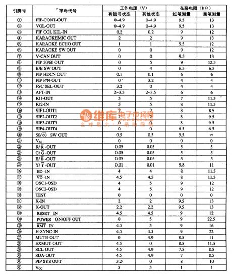
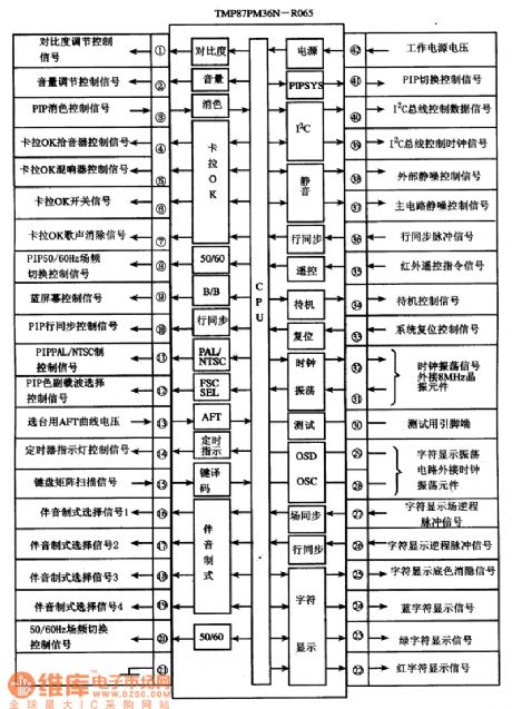
TMP87PM36N-R065 is a single-chip microcomputer integrated circuit produced by Toshiba company, it is widely used in Haier, Toshiba, and other large-screen color TV applications.
1. Features of function
TMP87PM36N-R065 is mainly composed of the central processing unit (CPU), clock oscillator circuit, the reset control circuit, remote command signal processing circuit, the key bits command signal decoding circuit, I2C bus control circuit, audio format control circuit, the screen display characters signal generation and processing circuit, and other control and ancillary functions circuits, the internal circuit block diagram is shown as the chart.
The circuit block diagram and pin functions and signal flowing of TMP87PM36N-R065 integrated circuit 2. Pin functions and data TMP87PM36N-R065 uses 42-pin dual in IC-style package, the pin functions and signal flowing is shown as Figure, the pin letters code and data are listed in Table. TMP87PM36N-R065 IC pin letter code and data
(View)
View full Circuit Diagram | Comments | Reading(778)
Wiretapping amplifier circuit
Published:2011/6/29 3:08:00 Author:zj | Keyword: Wiretapping, amplifier
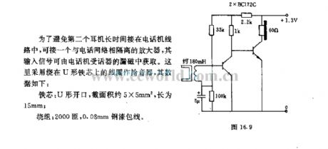
In order to avoidthat the second headset connects tothe telephone line for a long time,it can access in an isolated amplifier from the telephone network , the input signal can be obtained by the magnetic flux leakage of the telephone receiver.It usescoil around the U-shaped core for the pickuper, the data are as follows:
Core:U shaped port,the Cross-sectional area is about 5mm*5mm,the lenth is 15mm;
Winding:2000 turns,0.08mm steel wire. (View)
View full Circuit Diagram | Comments | Reading(844)
Weak signal amplifier circuit diagram composed of magnetosensitive resistance
Published:2011/5/16 3:12:00 Author:Nicole | Keyword: weak signal, amplifier, magnetosensitive resistance
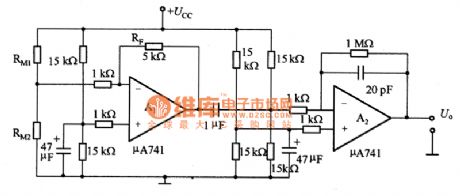
The figure 1 is a weak signal amplifier circuit which is composed of magnetosensitive resistance. About the paper currency recognizing device which is composed of RM1 and RM2, its output singal is small just about 0.4mV, so, itshould adopt the amplifier with more than 200 times. The adopted amplifier is shown in the figure1, the key of amplifier design is the temperature drift of reference voltage. Al is DC amplifier, RF is feedback resistance. It also is the AC amplifier of capacity coupling, the time constant selects low frequency signal approved resistance and capacity value. This circuit can not amplify the quiescent singal, but it can amplify the singal which is detected by the slow moving magnetosensitive resistance.
(View)
View full Circuit Diagram | Comments | Reading(918)
Free operation trigger circuit
Published:2011/7/17 1:25:00 Author:Fiona | Keyword: trigger, Free operation
View full Circuit Diagram | Comments | Reading(723)
| Pages:174/250 At 20161162163164165166167168169170171172173174175176177178179180Under 20 |
Circuit Categories
power supply circuit
Amplifier Circuit
Basic Circuit
LED and Light Circuit
Sensor Circuit
Signal Processing
Electrical Equipment Circuit
Control Circuit
Remote Control Circuit
A/D-D/A Converter Circuit
Audio Circuit
Measuring and Test Circuit
Communication Circuit
Computer-Related Circuit
555 Circuit
Automotive Circuit
Repairing Circuit