
Index 179
MB311O.MB3110A -Dual channel volume and balance control integrated circuit
Published:2011/7/13 19:46:00 Author:leo | Keyword: Dual channel volume, balance control, integrated circuit
MB
311O and MB3110A are dual channel volume and balance control integrated circuits made by MITSUBISHI in Japan.
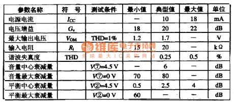
1.MB3110/A inner circuit diagram and pin functions:The integrated circuit MB3110/A contains a dual channel volume and balance control amplifying circuit which offers 20dB inner PRE out. Volume and balance are controlled by the change of reversed voltage. This circuit has the following features: Possessing the same voltage with power supply, big damping capacity of volume and balance control and so on. Its inner circuit diagram and pin functions are shown in the picture. 2.MB3110/A Main parameters:Under Ta is 25℃: Power supply voltage Vcc is 16 V (max); Control voltage Vcomt is 0 to Vcc, Power Consumption(allowed) is 530 mW. (View)
View full Circuit Diagram | Comments | Reading(1235)
The simple fan fault detection circuit
Published:2011/7/14 6:43:00 Author:Borg | Keyword: fan fault, detection circuit
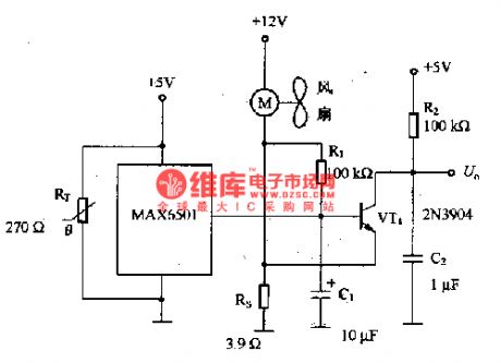
After the circuit is added with a thermistor switch MAX6501, if the system temperature is higher than the regulated value, then it will warn to replace the fan fault detector. RT thermistor should be close to MAX6501 when it is connected in, and it is located in the fan wind, so the fault of stopping running can be detected quickly, the reason is that when the fan is not running, there won't be air to pass RT and MAX6501. The circuit is not fitted in the fan with the closed lock rotator detector. If a fan is fixed with a rotator, the fan will restart in 0.5-1S after it stops. (View)
View full Circuit Diagram | Comments | Reading(1525)
L4962A--the efficient DC-DC converting integrated circuit of single chip
Published:2011/7/12 2:10:00 Author:Borg | Keyword: single chip, integrated circuit

1.function featuresThe switching efficiency of L4962A is about 80%, the working frequency is over 100MHZ, it has very few external elements, and its output current can be 1.5V, the output voltage can also be regulated in the range of 5-OV. It contains the precise voltage basic pole, fault amplifier, comparator and power switch, and it also includes the slow starting, max current limit and over heat protection circuit, etc. The typical application circuit of it is shown in figure 1-1.
2.pin function and dataL4962A is in the 16-pin dual in-line package.
(View)
View full Circuit Diagram | Comments | Reading(1639)
L78MRO5FA--the stable and reset integrated circuit
Published:2011/7/12 1:40:00 Author:Borg | Keyword: integrated circuit
L78MRO5FA is a stable and reset integrated circuit, which is widely used in the large screen color TV sets, stereo system of home theatre, computer display system, home PC systems, etc.1.function featuresL78MRO5FA consists of 2 parts, one of them is the regulated circuit, which is used to provide proper PC chip with power after the voltage (input from 1-pin) is regulated into 5V, the other part is the reset circuit, which is to reset the microcomputer.
(View)
View full Circuit Diagram | Comments | Reading(565)
L78LRO5-the regulated integrated circuit with function of reset
Published:2011/7/12 3:25:00 Author:Borg | Keyword: regulated integrated circuit, reset
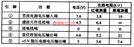
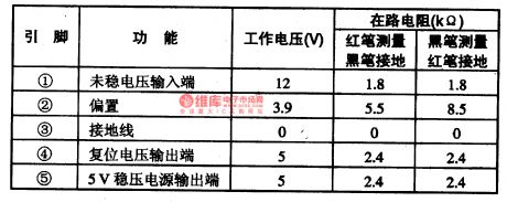
L78LRO5 is a regulated integrated circuit with function of reset, which is widely used in all types of large screen color TV sets.1.function featuresL78LRO5 consists of the reset circuit, +5V power supply regulated circuit and so on.2.pin functions and dataWhen L78LRO5 is installed in Sony Kv-K29MFl TV sets, its pin functions and data are listed in table 1-1.Notes: L78LRO5 can be replaced by L78LRO5D, L78MO5A, L78LR05-/mA, L78MRO5 and L78MRO5FA directly.
Table 1-1. the pin functions and data of L78LRO5
(View)
View full Circuit Diagram | Comments | Reading(856)
KS5308--the communication single chip computer integrated circuit
Published:2011/7/12 1:31:00 Author:Borg | Keyword: communication, single chip computer
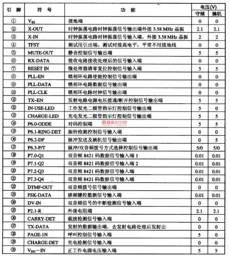
KS5308 is a communication single chip computer integrated circuit, which is used in wireless phones as the host micro processors.1.function features KS5308 contains sub-circuits of all kinds of control signal input/output circuit, the reception detection and transition of all kinds of signals and channel selection, processor of callers' signal, ring control, indicator control, phase-lock signal process circuit, charging detection, wave detection, puls/dual audio compatible dialing and other function circuits.2.pin functions and data
(View)
View full Circuit Diagram | Comments | Reading(591)
KS57C2304--the communication single chip microcomputer integrated circuit
Published:2011/7/12 2:54:00 Author:Borg | Keyword: communication, single chip, microcomputer, integrated circuit
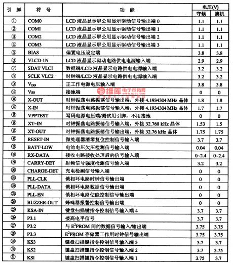
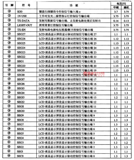
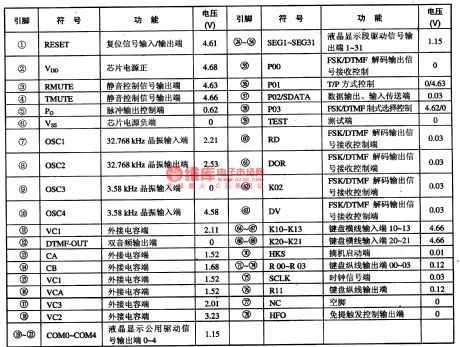
1.function featuresKS57C2304 contains the input/output circuit of all kinds of signals, keypad input circuit, reception and emitting circuit of all the signal orders, caller signal process circuit, 2 teams of clock oscillating circuit, LCD drive control circuit and other function circuits.2.pin functions and dataKS57C2304 is in the 64-pin dual in-line package, whose pin functions and data are listed in table 1-1.Notes: KS57C2304 has the function of battery low voltage and charge detection.
(View)
View full Circuit Diagram | Comments | Reading(627)
KCM-201--the communication single chip microcomputer integrated circuit
Published:2011/7/12 1:59:00 Author:Borg | Keyword: communication single chip, microcomputer, integrated circuit
KCM-201 is the communication single chip microcomputer integrated circuit, which is often used in caller display phones.1.function featuresKCM-201 contains the FSK/DTMF signal process circuit, pulse/dual audio with dialing circuit, LCD drive control circuit, key switch signal encoding circuit, hand free control circuit, mute control circuit and other control function circuit. Table 1-1 pin functions and data of KB2511
2.pin functions and dataKCM-201 is in 74-pin soft package.
(View)
View full Circuit Diagram | Comments | Reading(698)
The CXA1033P AM single chip radio integrated circuit
Published:2011/7/11 21:39:00 Author:Borg | Keyword: single chip, integrated circuit
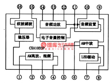
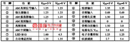

CXA1033P is an AM single chip radio circuit which is produced by Sony, which is used in the low-voltage radio and recorder. 1.the internal circuit and pin functions of CXA1033P CXA1033P includes the AGC, mix, INTREQ, detection, LED drive and audio pre-stage, audio power amplifier, etc. The internal circuit of the integrated chip is shown is figure 1. The IC is in 16-pin dual in-line package, whose pin functions and data are shown in figure 1, in figure 2 is the tested data of several radios composed of CXA1033P.
(View)
View full Circuit Diagram | Comments | Reading(3363)
The CXA1O19 AM single chip radio integrated circuit
Published:2011/7/11 22:10:00 Author:Borg | Keyword: single chip radio, integrated circuit
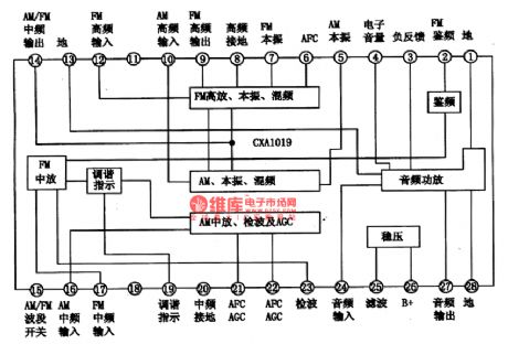
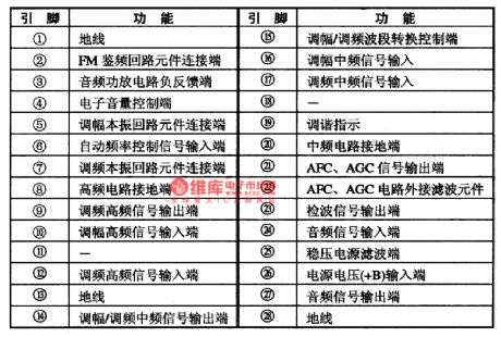
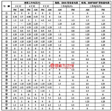
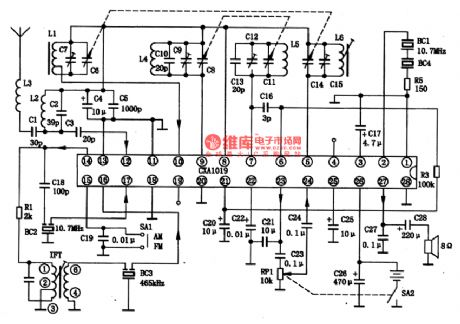
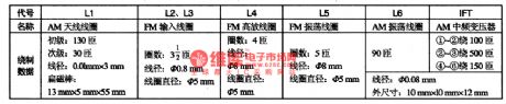
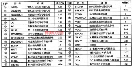
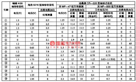
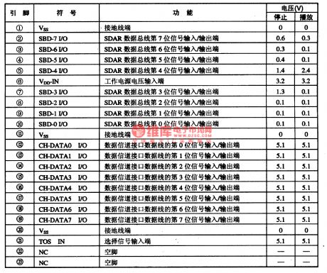
2. The internal circuit and pin functions of CXA1O19CXA1O19 is in 28-pin dual line plastic structure, whose internal circuit is shown in figure 1, and the pin function of the integrated circuit is shown in table 1. In table 21 are the typical static voltages when IC is at 3V, 6V and 9V and in AM or FM state respectively (in the table also lists the tested data of 2 models).
Figure 1 the internal circuit of CXA1O19
Table 1 the pin functions of the CXA1O19 single chip integrated circuit
Table 2 the tested data of the the CXA1O19 single chip integrated circuit
(View)
View full Circuit Diagram | Comments | Reading(1885)
The MPEG-2 and AC-3 decoding integrated circuit of L64021 single chip LS1
Published:2011/7/12 0:13:00 Author:Borg | Keyword: decoding, integrated circuit
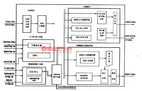

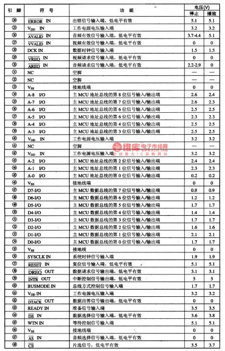

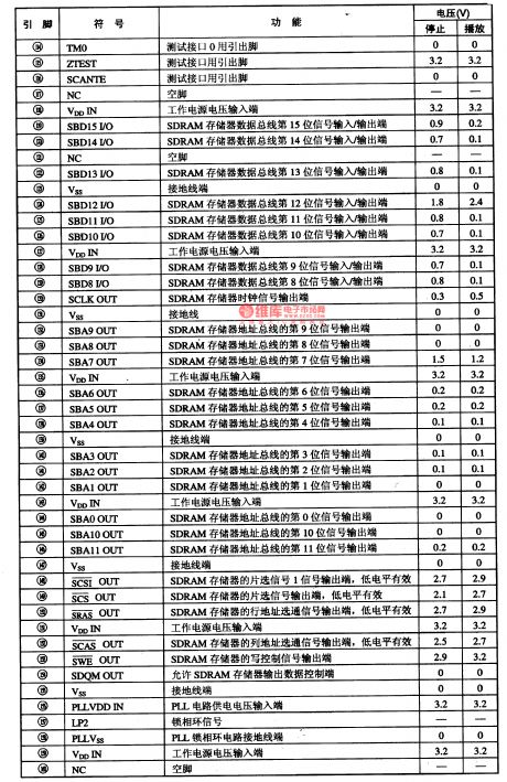
L64021 is a MPEG-2 single chip AV decoding integrated circuit produced by LSILOGIC, which combines the MPEG-2 and AC-3 decoder of LSI and CSS copyright protection circuit, it is a mass MPEG-2 decoding integrated circuit. It is compatible with VDC and CD-ROM form, and it is widely used in DVD players and multimedia PC, such as SONY DVD players, etc. 1.the functions of L64021 internal circuit In figure 1-1 is the internal structure principle circuit of L64021, which consists of the main CPU connection circuit, data channel connector circuit and so on.
(View)
View full Circuit Diagram | Comments | Reading(1013)
SAAl25l (TV set) infrared remote control receiving amplifier circuit
Published:2011/7/12 8:13:00 Author:Christina | Keyword: TV set, infrared, remote control, receiving amplifier
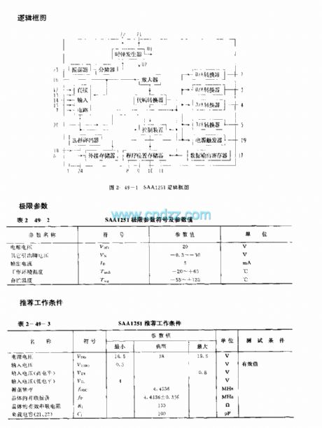
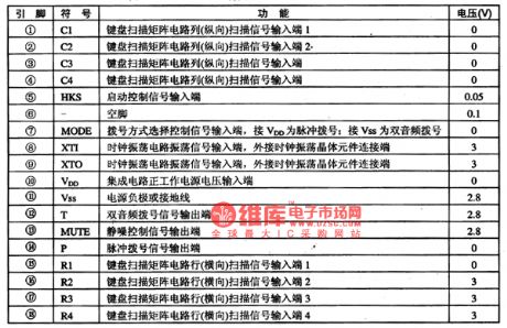
The SAA1251 is designed as one kind of infrared remote control receiving amplifier P-channel Si integrated circuit, and it can be used in the TV set application. The internal circuit is composed of the oscillator, the clock signal generator, the amplifier, the frequency divider, the direct input circuit, the code converter, the selective decoder, the control device, the D/A converter, the power trigger, the program location memory and the data output register.
(View)
View full Circuit Diagram | Comments | Reading(574)
CH25610--the pulse/dual audio dialing integrated circuit
Published:2011/7/13 10:55:00 Author:Borg | Keyword: dual audio dialing, integrated circuit
CH25610 is a the pulse/dual audio dialing integrated circuit, which is used in communication dialing control circuits, and it is often used in wire/wireless phones.1.function featuresCH25610 contains pulse/dual audio with dialing, keypad switch signal encoding/decoding and other function circuits.2.pin functions and dataPin functions and data of CH25610 are listed in table 1.
Table 1. Pin functions and data of CH25610 (View)
View full Circuit Diagram | Comments | Reading(681)
Integrated power amplifer application reference circuit
Published:2011/7/13 10:16:00 Author:Nancy | Keyword: Integrated power amplifer, Application reference circuit
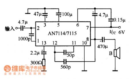

AN-7114/7115 application circuit is shown as above.
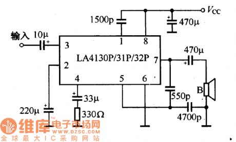
LA4130P/31P/32P application circuit is shown as above.
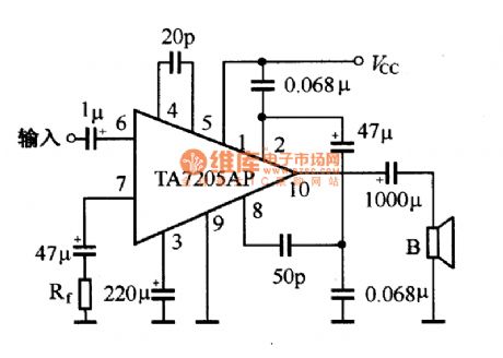
T
A7205AP application circuit
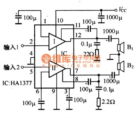
HA1377 application circuit
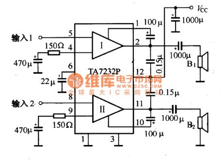
TA7232P application circuit
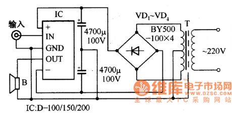
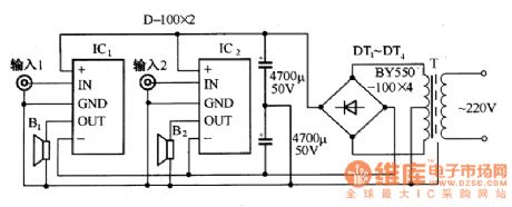
Using D series integrated power amplifier can form a mono OTL or OCL audio power amplifier easily, which is shown as the figure. If you use two pieces of D series integrated power amplifier, you can form dual channel power amplifier convenient, which is shown in figure.
single power supply OCL power amplifier circuit
single power supply OTL power amplifier circuit
dual channel OCL power amplifier circuit (View)
View full Circuit Diagram | Comments | Reading(2550)
500MHZ Broadband Amplifier Circuit
Published:2011/7/13 6:07:00 Author:Sue | Keyword: Broadband, Amplifier
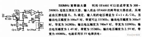
As seen in the figure is the 500MHZ broadband amplifier circuit. OPA660 can be used to compose direct feedback amplifier with a bandwidth of 500MHz. The input stage consists of OPA660 transconductance amplifier whose gain is decided by feedback resistor R3,R5. Its input stage's voltage gain is G=1+R3/2R5. When the output voltage range is 100mV, the broad width can reach 331MHz; When the output voltage range is 300 mV, the broad width is 362MHz; When the output voltage range is 700mV, the broad width is 520MHz; When the output voltage range is 1.4v, the broad width is 552MHz; When the output voltage range is 2.5v, the brand width is 490 MHz. The circuit uses double 5v as power supply. (View)
View full Circuit Diagram | Comments | Reading(517)
50KHZ Broadband Amplifier Circuit
Published:2011/7/13 6:17:00 Author:Sue | Keyword: Broadband, Amplifier
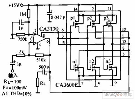
The amplifier with a brand width of 50KHz put CA3600 transistor array paralleling output circuit on the operational amplifier CA3130's output stage. Then the current control ability can improve 2.5 times. The closed-loop gain is 48dB and the brand width is 50KHz. (View)
View full Circuit Diagram | Comments | Reading(990)
400MHZ Differential Amplifier Circuit
Published:2011/7/13 6:31:00 Author:Sue | Keyword: Differential, Amplifier
In the figure, it is the 400MHz differential amplifier. The brandbroad operational transconductance amplifier, the buffer OPA660 can compose differential amplifier with a brand width of 400MHz. The high speed buffer amplifier BUF601 serve as buffer output stage. The circuit gain G=R9/(R8+1/gm). In the formula, gm is OPA660 transconductance's transconductance gain. When R16=650Ω, OPA660's quiescent current is about 10mA and the transconductance is about 0.08A/V(see the figure 1.112). (View)
View full Circuit Diagram | Comments | Reading(464)
The joint circuit between MMA1260D and ATmega8L
Published:2011/7/7 6:39:00 Author:Ariel Wang | Keyword: joint, MMA1260D, ATmega8L
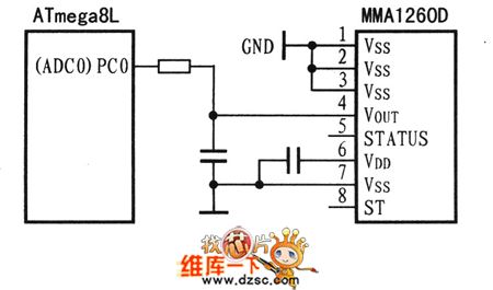
Acceleration sensor for MMA1260D collects the data of mobile acceleration. And it goes through the port of PC0 of ATmega8L(ADC0) to ATmega8L. It forms a direct ratio of the output voltage and the acceleration of MMA1260D's acceleration sensor. For measuring the output voltage of acceleration sensor,usually we use microcontroller with A/D. For specific connection,see chart. There is a filter between VOUT and the RC of A/DIN's pin.It is used for reducing the noise of the clock. There is no strong electric current between acceleration sensor and microcontroller.The 0.1μF capacitance between power-supply and ground is the decoupling capacitance. (View)
View full Circuit Diagram | Comments | Reading(662)
The circuit of download line for AT89S52
Published:2011/6/13 7:14:00 Author:Ariel Wang | Keyword: download line , AT89S52

By analysing parallel port and programming time sequence,we made ISP download cable of MCU for AT89S5X. We make a brief introduction of parallel port and the connecting line of ACU. The pin of the parallel port of P2 is connected to P1.5'spin(MOSI) of MCU .The parallel port P10's pin is connected to P1.6's pin of MCU(MISO). The parallel port P1's pin is connected to P1.7's pin of MCU(SCK). The parallel port P17's pin is connected to RST's pin of MCU. See the chart above.
(View)
View full Circuit Diagram | Comments | Reading(1754)
FET bandwidth amplifier circuit
Published:2011/7/10 2:27:00 Author:leo | Keyword: FET, Bandwidth, Amplifier circuit

Picture 1 shows a FET bandwidth amplifier circuit. In this circuit, VT1 and VT2 are bumpers. VT1 is used as source follower, while VT3 and VT4 are used to amplifying voltage and VT5 and VT6 have the function of power amplifying. A1 is DC feedback circuit which is used to stabilize the circuit. And A1 compares the output signals and input signals and amplifies the difference of them. The amplified signals offer differential to VT2, as a result, VT1 channel current is permitted to form a circle. And this demands that the UGS of VT1 should be matched with input and output voltage of the circuit. (View)
View full Circuit Diagram | Comments | Reading(1133)
| Pages:179/250 At 20161162163164165166167168169170171172173174175176177178179180Under 20 |
Circuit Categories
power supply circuit
Amplifier Circuit
Basic Circuit
LED and Light Circuit
Sensor Circuit
Signal Processing
Electrical Equipment Circuit
Control Circuit
Remote Control Circuit
A/D-D/A Converter Circuit
Audio Circuit
Measuring and Test Circuit
Communication Circuit
Computer-Related Circuit
555 Circuit
Automotive Circuit
Repairing Circuit