
Index 166
RIAA_LINE_AMPLIFIER_DRIVER
Published:2009/6/18 23:45:00 Author:May
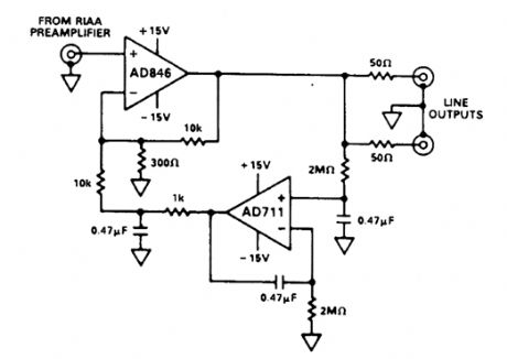
Two op amps by Analog Devices are used in this audio Iine amplifier, which is suitable for interfacing with an RIAA preamplifier. (View)
View full Circuit Diagram | Comments | Reading(899)
TRANSISTOR_RIAA_PREAMP_FOR_MAGNETIC_PHONE_CARTRIDGES
Published:2009/6/18 23:42:00 Author:May

This two-transistor circuit has around 40 dB (midband) gain at 1 kHz. A magnetic cartridge is used as a source. (View)
View full Circuit Diagram | Comments | Reading(1767)
PERSONAL_STEREO_AUDIO_AMP
Published:2009/6/18 23:40:00 Author:May
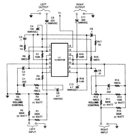
You can make your personal stereo do double duty as a small room stereo by adding this 2-watt amplifier. (View)
View full Circuit Diagram | Comments | Reading(813)
TWO_TRANSISTOR_AUDIO_AMPLIFIER
Published:2009/6/18 23:39:00 Author:May
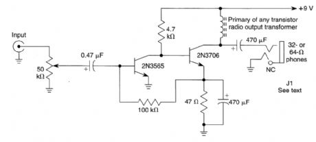
This is a general-purpose audio ampliffier for driving a pair of stereo earphones in monaural mode.Two can be used for stereo. In this case, ground the centei top of the earphone (sleeve of J1). (View)
View full Circuit Diagram | Comments | Reading(972)
NB_FM_AUDIO_AMPLIFIER
Published:2009/6/18 23:36:00 Author:May
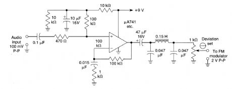
This audio system amplifies, limits, and filters an audio voice signal for use with an FM modulator or VCO. It has pre-emphasis of 6-dB/octave 800-3000Hz. Almost any suitable op amp can be used. (View)
View full Circuit Diagram | Comments | Reading(2058)
MICROPOWER_LINEAR_AMPLIFIER
Published:2009/6/18 23:34:00 Author:May
This circuit, based on the inverter in the CD4007UB CMOS linear amplifier, shows a method for reducing drain current. (View)
View full Circuit Diagram | Comments | Reading(666)
VACUUM_TUBE_AUDIO_AMPLIFIER
Published:2009/6/18 23:33:00 Author:May
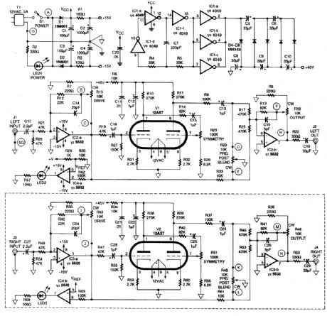
This schematic is for a tubehead amplifier. The output from transformer T1 is positive half-wave ac rectified by Dl and filtered by C1, C2, and RI for a +15-V supply. A -15-V supply is avail-able from D2, C3, C4, and R3. The plate supply for the 12AX7 tubes is produced by a voltage multi-plier.Some listeners prefer the sound of a vacuum tube audio system. Although this is rather subjective and a personal preference, this circuit can be used to simulate the tube sound preferred by these listeners. (View)
View full Circuit Diagram | Comments | Reading(1012)
TUNABLE_FM_ANTENNA_BOOSTER
Published:2009/6/18 23:16:00 Author:May

This two-transistor amplifier circutt with tunable Lank circuits boosts Lhe distant FM signals Coils L1 and L2 are 1 1/2 turns#20 AWG bail tinned wtre wound around a 2/3 diameter mandrel. (View)
View full Circuit Diagram | Comments | Reading(3380)
Little Modifying Tianpeng AP-321 Power Amplifier Circuit
Published:2011/7/28 17:45:00 Author:Robert | Keyword: Modifying, Tianpeng, Power Amplifier
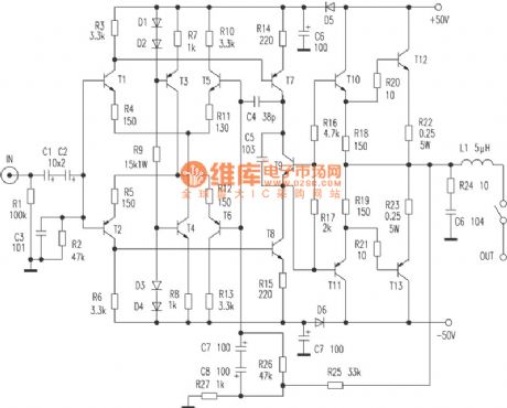
Openning its case, the resistances are all five-ring metal films, dozens of red CBB small capacitors are high-quality. And the key places even use the sanyo 105℃ electrolytic capacitor. The coupling capacitors are two ELNA no-polarity series normal products. The audio source switch uses the long-axis switch. The kara OK chip uses the Japanese Mitsubishi company's M50195P. The large-power output tube is Toshiba company's 2SC3280 and 2SA1301. When modifying the machine later it alse find that all triodes and resistances have been strictly paired. The back board has two groups of output ports which could connect to a couple of speakers at the same time. It can uses the a switch on front board for AB contrast audition. The Kara OK and the tone stage all have the switchs. When they are not used they could be closed to avoid the bad effects on the sound quality, which is very practical. (View)
View full Circuit Diagram | Comments | Reading(2797)
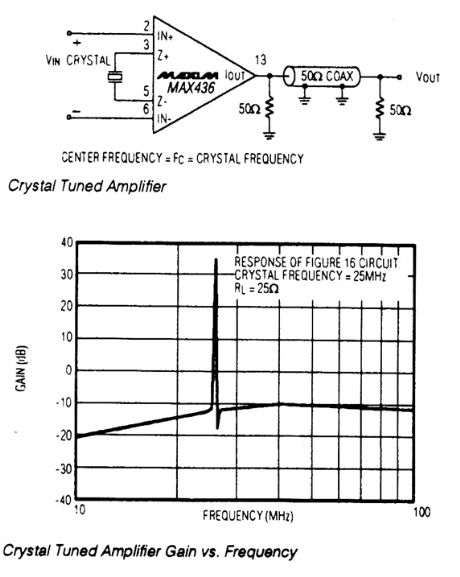
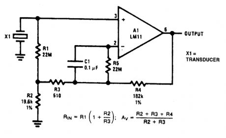
CRYSTAL_TUNED_AMPLIFIER
Published:2009/6/18 22:50:00 Author:May
View full Circuit Diagram | Comments | Reading(544)
BANDPASS_AMPLIFIER
Published:2009/6/18 22:38:00 Author:May
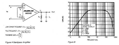
The circuit A is a bandpass amplifier,with the low corner frequency set by the impedance of the transconductance network,The high corner frequency IS set by the impedance ofthe RC network atthe amplifier output The passband gatn is (k)x (R1/RT). Figure B is a plot ofthe circuit in Figure A,with Rt=100Ω,Ct=20nF,R1=25Ω,and C1=395pF. (View)
View full Circuit Diagram | Comments | Reading(839)
BASIC_LOGARITHMIC_AMPLIFIER_USING_OP_AMP
Published:2009/6/18 22:49:00 Author:May
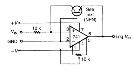
This logarithmic arnplifier uses a single op amp. The current in the feedback loop of the op amp ts equal to the current flow at the input of the op amp. (View)
View full Circuit Diagram | Comments | Reading(1308)
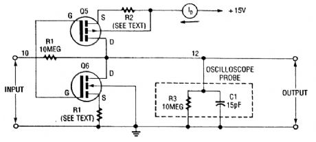
MOSFET_PUSH_PULL_AMPLIFIER
Published:2009/6/18 22:40:00 Author:May
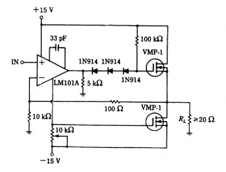
This amplifier can be used for audio or as a driver for inverter service. (View)
View full Circuit Diagram | Comments | Reading(1099)
HIGH_INPUT_IMPEDANCE_ac_AMPLIFIER
Published:2009/6/18 22:39:00 Author:May


This figure shows an op amp used as an ac amplifier. It is unusual in that dc bootstrapping is used to obtain high input resistance without requiring high-value resistors. In theory, this increases the output offset because the op amp offset voltage is multiplied by the resistance boost.But when conventional resistor values are used, it is practical to include R5 to eliminate bias-current error. This gives less output offset than if a single, large resistor were used. C1 is included to reduce noise. (View)
View full Circuit Diagram | Comments | Reading(1281)
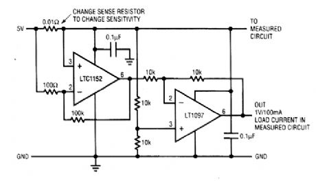
HIGH_SIDE_CURRENT_SENSING_AMPLIFIER
Published:2009/6/18 22:38:00 Author:May
View full Circuit Diagram | Comments | Reading(752)
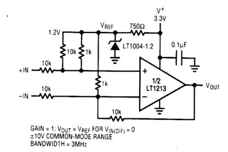
DIFFERENCE_AMPLIFIER_WITH_WIDE_INPUT_COMMON_MODE_RANGE
Published:2009/6/18 22:34:00 Author:May
View full Circuit Diagram | Comments | Reading(602)
TUNED_AMPLIFIER
Published:2009/6/18 22:33:00 Author:May
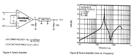
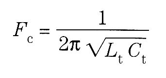
This circuit is a tuned amplifier circuit, tuned to the resonant frequency of the LC transconduc-tance network: The impedance of the transconductance network is a minimum at the resonant frequency, providing maximum amplifier gain at that frequency. The Q of the amplifier is a function of the parasitic components associated with the LO network. The graph is the frequency response of the circuit, with Lt=2.93 μH and Ct=9.9 pF. (View)
View full Circuit Diagram | Comments | Reading(1218)
VOICE_ACTIVATED_SWITCH_AND_AMPLIFIER
Published:2009/6/18 22:31:00 Author:May
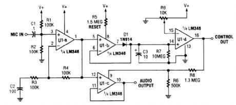
In certain applications, such as transmitter or other communications and control applications, this circuit should be useful. Both audio output and dc control outputs are provided. R9 sets the con-trol threshold. (View)
View full Circuit Diagram | Comments | Reading(1741)
REMOTELY_POWERED_SENSOR_AMPLIFIER
Published:2009/6/18 22:31:00 Author:May
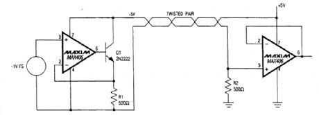
For rerrtote sensor applications, this circuit enables use of a single twisted pair. (View)
View full Circuit Diagram | Comments | Reading(1128)
PROGRAMMABLE_INPUT_AMPLIFIER
Published:2009/6/18 22:30:00 Author:May
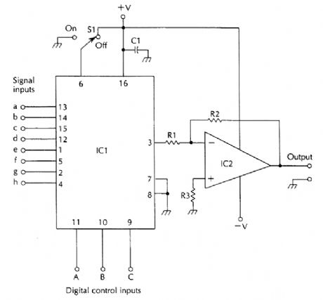
This amplifier has eight inputs selectable digitally.
IC1 CD4051 SP8T bilateral switch R1 10-kΩ 1/4-W 5% resistorIC2 Op amp to suit application R2 22-kΩ 1/4-W 5% resistorC1 0.1-μF capacitor R3 18-kΩ 1/4-W 5% resistorS1 SPST switch (View)
View full Circuit Diagram | Comments | Reading(1568)
| Pages:166/250 At 20161162163164165166167168169170171172173174175176177178179180Under 20 |
Circuit Categories
power supply circuit
Amplifier Circuit
Basic Circuit
LED and Light Circuit
Sensor Circuit
Signal Processing
Electrical Equipment Circuit
Control Circuit
Remote Control Circuit
A/D-D/A Converter Circuit
Audio Circuit
Measuring and Test Circuit
Communication Circuit
Computer-Related Circuit
555 Circuit
Automotive Circuit
Repairing Circuit