
Index 167
PROGRAMMABLE_GAIN_AMPLIFIER
Published:2009/6/18 22:13:00 Author:May

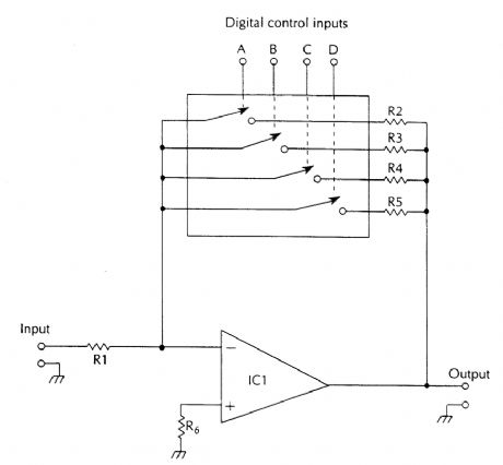
The gain of this amplifier is-Rf/R1 where Rf=effective value of resistance selected by the digital R1 inputs.IC1 op ampIC2 CD4066 quad bilateral switchR1 1-kΩ,1/4-W 5% resistorR2 10-kΩ,1/4-W 5% resistorR3 4.7-kΩ,1/4-W 5% resistorR4 2.2-kΩ,1/4-W 5% resistorR5 1-kΩ,1/4-W 5% resistorR6 2.2-kΩ,1/4-W 5% resistor (View)
View full Circuit Diagram | Comments | Reading(2529)
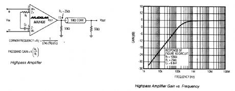
HIGHPASS_AMPLIFIER
Published:2009/6/18 21:55:00 Author:May
View full Circuit Diagram | Comments | Reading(700)
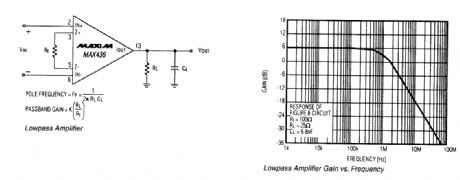
LOWPASS_AMPLIFIER
Published:2009/6/18 21:54:00 Author:May
View full Circuit Diagram | Comments | Reading(674)
OPERATIONAL_TRANSCONDUCTANCE_AMPLIFIER_WITH_BOOSTER
Published:2009/6/18 21:50:00 Author:May
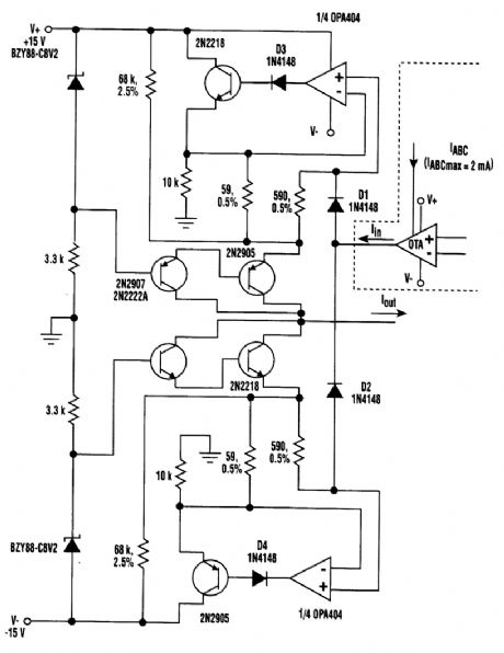
Implementing a bidirectional precision current amplifier in an operational transconductance am-plifier (OTA) can boost the OTA's output current. To accomplish this task, two diodes and a comple-mentary stage are added to this otherwise simple design. (View)
View full Circuit Diagram | Comments | Reading(1086)
PRECISION_HIGH_GAIN_DIFFERENTIAL_AMP
Published:2009/6/18 4:10:00 Author:May
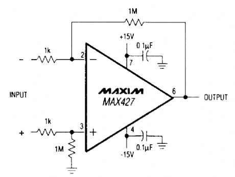
This circuit has a galn of 60 dB and a gatn bandwidth of 8 MHz. (View)
View full Circuit Diagram | Comments | Reading(678)
BASIC_OP_AMP_DIFFERENTIAL_AMPLIFIER
Published:2009/6/18 4:07:00 Author:May

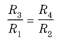
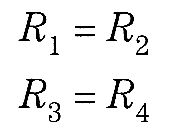

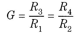
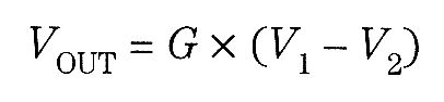


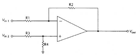


In most cases, R1 is equal to R2 and R3, has the same value as R4 These equalities don't always have to be true, but they do significantly simplify the circuit design in most practical applications. In any case, for a true differential amplifier, the R3,:R1and R2;R4 ratios must be equal. That is:The circuit still functions even if these ratios are not maintained, but the signals at the inverting and noninverting inputs are subjected to differing amounts of gain, which would be undesirable in most practical applications.These resistance ratioi determine the gain of the amplifier:Assuming that the resistance ratios are maintained, the output voltage is equal to the differences between the two input voltages, multiplied by the gain. That is, (View)
View full Circuit Diagram | Comments | Reading(1000)
RF_PREAMPLIFIERS
Published:2009/6/18 2:27:00 Author:May
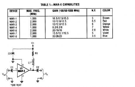
In this basic MAR-x-based circuit, both the input and output are comprised of a single dc-blocking capacitor (C1 and C2 for the input and output, respectively). The dc power-supply net-work (comprised of L1 and BI) is attached to the MAR-x via the RF-output terminal (lead 3). (View)
View full Circuit Diagram | Comments | Reading(982)
LC_TUNED_AMPLIFIERS
Published:2009/6/18 2:17:00 Author:May
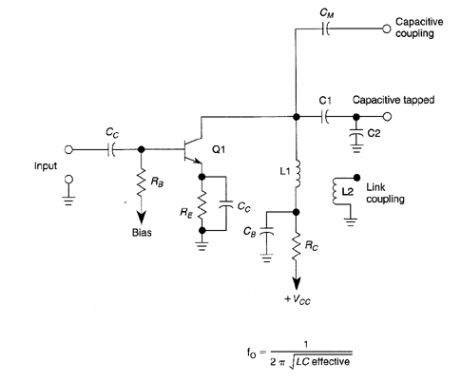
This basic tuned LC amplifier can be used with three output coupling methods. They are capac-itive coupling output, capacitive tapped output, or Iink-coupled output. (View)
View full Circuit Diagram | Comments | Reading(1365)
5_W_7_MHz_RF_POWER_AMPLIFIER
Published:2009/6/18 2:16:00 Author:May
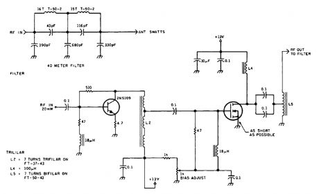
The circuit shown will produce up to 5-W RE output in the 40-m (7 MHz) amateur band. The coils shown are wound on toroidal cores (Armdon Associates Inc.). The part numbers are given in the schematic. The circuit requires about 20-mW drive and a 13-V supply. (View)
View full Circuit Diagram | Comments | Reading(778)
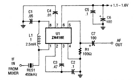
455_kHz_IF_AMP_FOR_15_V_OPERATION
Published:2009/6/18 2:11:00 Author:May
The ZN416E can be configured as a simple 455-kHz IF amplifier. In this case, the circuit's center and bandwidth are set by RES1 (a Murata CSB455E ceramic resonator). (View)
View full Circuit Diagram | Comments | Reading(1912)
SWITCHABLE_HF_VHF_ACTIVE_ANTENNA
Published:2009/6/18 2:10:00 Author:May
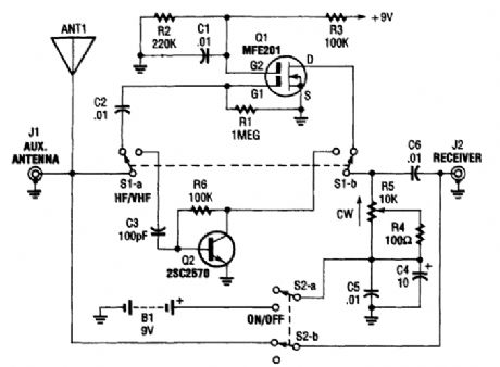
The AA-7 active antenna contains only two active elements: Q1 (an MFE201 N-channel dual-gate FET) and Q2 (a 2SC2570 npn VHF silicon transistor), which provide the basis of two indepen-dent, switchable RE preamplifiers. (View)
View full Circuit Diagram | Comments | Reading(2945)
12_kW_144_MHz_LINEAR_AMPLIFIER
Published:2009/6/18 2:09:00 Author:May
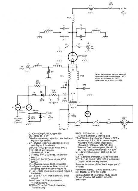
Schematic diagram ofthe 2-meter amplifier (View)
View full Circuit Diagram | Comments | Reading(957)
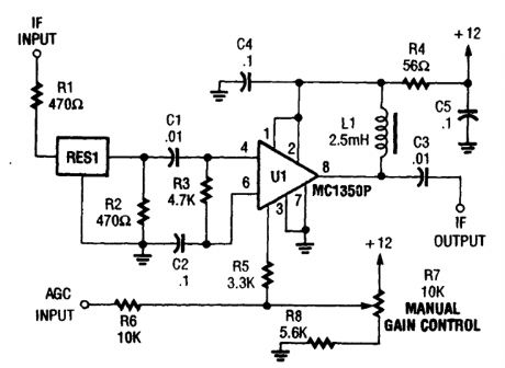
455_kHz_IF_AMPLIFIER
Published:2009/6/18 2:01:00 Author:May
Up to bU dB of gam at 455 kHz is available with the MC1350P. RES1 is a ceramic resonator, LC, or crustal filter. Keep the leads to pins,1, 2, 3, and 7 short. (View)
View full Circuit Diagram | Comments | Reading(2197)
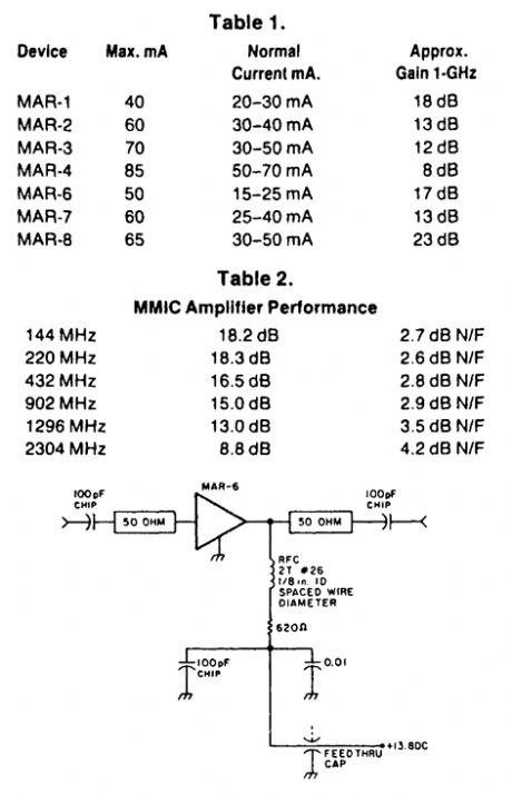
144__TO_2304_MHz_UHF_BROADBAND_AMPLIFIER
Published:2009/6/18 1:57:00 Author:May
Based on an MAR-6 preamp, this circuit yields low noise figures and useful gain for the 144-MHz to 2304-MHz amateur bands. (View)
View full Circuit Diagram | Comments | Reading(708)
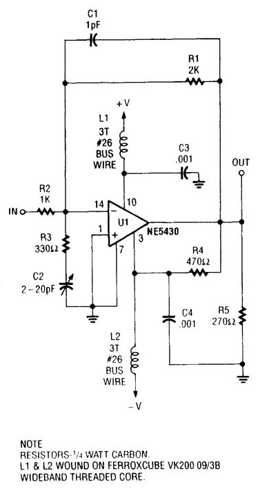
UHF_AMPLIFIER
Published:2009/6/18 1:55:00 Author:May
View full Circuit Diagram | Comments | Reading(730)
SIMPLE_455_kHz_IF_AMPLIFIER
Published:2009/6/18 1:54:00 Author:May

The ZN416E can be configured as a simple 455-kHz IF amplifier. In this case, the drcuit's center frequency and bandwidth are set by RES1 (a Murata CSB455E ceramic resonator). (View)
View full Circuit Diagram | Comments | Reading(3148)
20_W_1296_MHz_AMPLIFIER_MODULE
Published:2009/6/18 1:53:00 Author:May
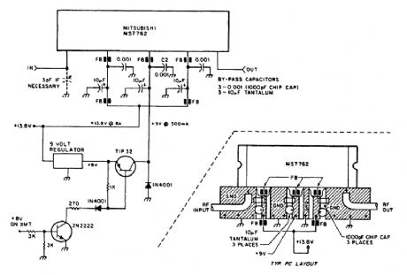
Using a Mitsubishi M57762 amplifier module, this amplifier delivers 20-W output on 1296 MHz. A single 12-V nominal power supply can be used. (View)
View full Circuit Diagram | Comments | Reading(3478)
2_METER_FET_POWER_AMPLIFIER_FOR_HTs
Published:2009/6/18 1:48:00 Author:May
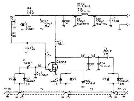
Using a power MOSFET, this amplifier can boast a 2-W handie-talkie power level to around 10 W on 2 meters. A transmission-line RE switch is used for T/R switching. (View)
View full Circuit Diagram | Comments | Reading(1067)
10_W_10_METER_LINEAR_AMPLIFIER
Published:2009/6/18 1:45:00 Author:May
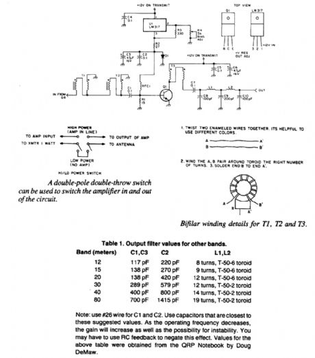
This linear amplifier delivers 10-W PEP output with 1.25-W drive on 10 m. T1, T2, and T3 are 10 turns of bifilar windings on an FT-50-43 toroidal core. The transformers are broadband. Filters for other bands, if desired, are shown. (View)
View full Circuit Diagram | Comments | Reading(1131)
WIDEBAND_POWER_AMPLIFIER
Published:2009/6/18 1:43:00 Author:May
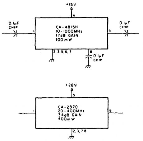
Using TRW P/N CA-815H, a 17-dB gain am-plifier that delivers 100 mW over 10 to 1000 MHz can be constructed. The CA-2870 will yield 0.4 W with 34-dB gain from 20 to 400 MHz. (View)
View full Circuit Diagram | Comments | Reading(804)
| Pages:167/250 At 20161162163164165166167168169170171172173174175176177178179180Under 20 |
Circuit Categories
power supply circuit
Amplifier Circuit
Basic Circuit
LED and Light Circuit
Sensor Circuit
Signal Processing
Electrical Equipment Circuit
Control Circuit
Remote Control Circuit
A/D-D/A Converter Circuit
Audio Circuit
Measuring and Test Circuit
Communication Circuit
Computer-Related Circuit
555 Circuit
Automotive Circuit
Repairing Circuit