
Index 173
INA326/327 precision Rail-Rail I/O instrumentation amplifier circuit
Published:2011/7/24 21:42:00 Author:Christina | Keyword: precision, Rail-Rail, I/O, instrumentation, amplifier circuit
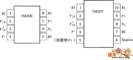
The INA326/327 (with the close function) is the high-performance, low price precision instrumentation amplifier circuit that has the input and output amplitudes of positive and negative power supply voltage (Rail-Rail), it has very low DC error and input common-model range which exceeds the positive and negative Rails, and it can be used in the range of the universal amplification to the high precision amplification. In the using period of products, the super long time stability and the low 1/f noise ensures the low offset voltage and drift. The INA326/327 can be used in the low level sensor amplification, the bridge circuit amplifier, the pressure components, the thermocouple amplification, the wide dynamic range sensor, the high resolution test system, the weight measurement, the multi-channel data acquisition, the medical instrument, the universal amplification.
(View)
View full Circuit Diagram | Comments | Reading(832)
CL484--T128--the audio/video decoding integrated circuit
Published:2011/7/15 19:15:00 Author:Borg | Keyword: audio/video decoding, integrated circuit
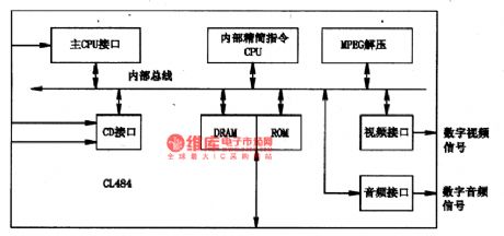
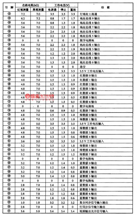
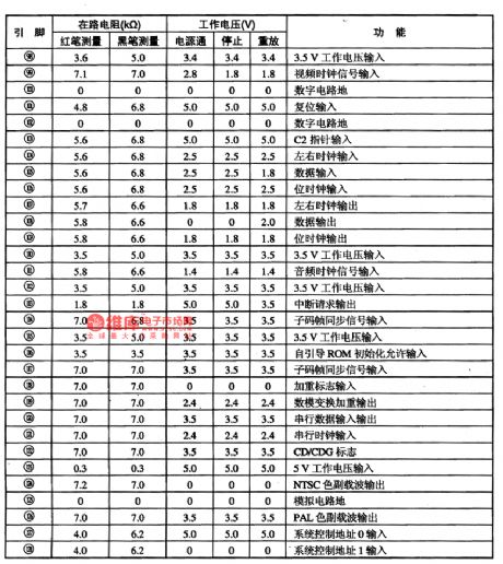
1.function featuresCU84 combines pictures and sound decoding circuit, whose main function is to switch the CD and CD-ROM mixed digit signals of MPEG-I standard compressing codes into the audio digital signals and video digital signals, so that the signals are easy to turn back to analog audio and video signals through audio and video D/A converting circuit. The circuit contains the CPU connector, CD connector, internal DRAM/ROM connector, MPEG-I decompressing unit, symbol generator (OSD), audio/video connector and other circuits. The internal circuit of the chip is shown in figure 1.
(View)
View full Circuit Diagram | Comments | Reading(737)
The 3-terminal voltage stabilizing integrated circuit
Published:2011/7/15 19:13:00 Author:Borg | Keyword: 3-terminal, integrated circuit
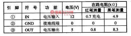
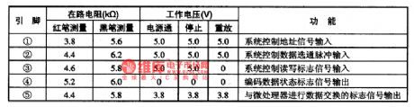
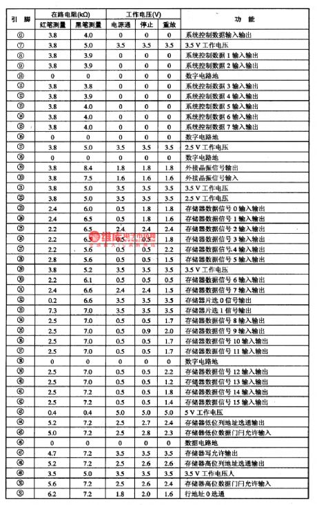
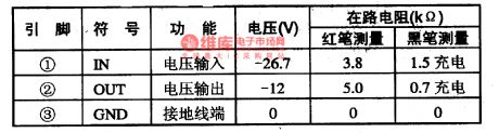
L7805 is a 3-terminal voltage stabilizing integrated circuit produced by Sanyo, which is widely used in the power supplies of all kinds of electric apparatus. When L7805 is used in Changhong Jingxian and Jingxianren projection TV sets, it pin functions and data are shown in table 1-1.
Table 1-1 the pin function and data of L7805 (View)
View full Circuit Diagram | Comments | Reading(618)
L7812--the 3-terminal voltage stabilizing integrated circuit
Published:2011/7/15 19:12:00 Author:Borg | Keyword: 3-terminal, integrated circuit
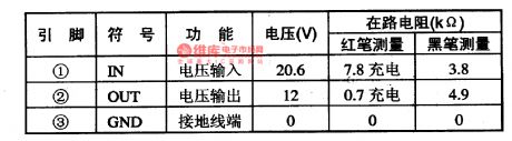
L7912 is the the 3-terminalvoltage stabilizingintegrated circuit produced by Sanyo, Japan, which is widely used in power supply circuits of all kinds of electric apparatus. When L7912 is used in Changhong clear and clear king projector color TV sets, its pin functions and data are listed in table 1-1.
Table 1-1 pin functions and data of L7812 (View)
View full Circuit Diagram | Comments | Reading(587)
L7912--the 3-terminal negative stable integrated circuit
Published:2011/7/13 23:12:00 Author:Borg | Keyword: 3-terminal, negative, stable, integrated circuit
L7912 is the 3-terminal negative stable integrated circuit produced by Sanyo, Japan, which is widely used in power supply circuits of all kinds of electric apparatus. When L7912 is used in Changhong clear and clear king projector color TV sets,its pin functions and data are listed in table 1-1.
Table 1-1 pin functions and data of L7912 (View)
View full Circuit Diagram | Comments | Reading(962)
The CXA1OO5P single chip stereo playback integrated circuit
Published:2011/7/15 19:09:00 Author:Borg | Keyword: single chip, playback
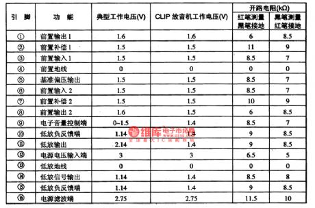
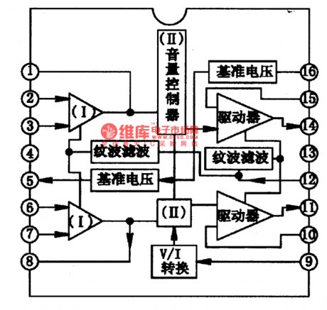
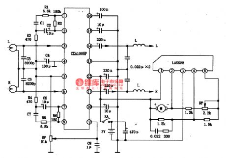
CXA1OO5P is a single chip stereo playback integrated circuit produced by Sony, which is used in ultra-small radios.1.the internal circuit and pin functions of CXA1OO5P CXA1OO5P is manufactured in dual-pole craft, which includes the preset balance amplifier, DC volume control circuit, headphone power drive stage and other function circuits. The internal circuit of the chip is shown in figure 1. The IC is in 16-pin dual in-line package, whose pin functions and data are listed in table 1.
table 1 pin functions and data of CXA1OO5P
(View)
View full Circuit Diagram | Comments | Reading(715)
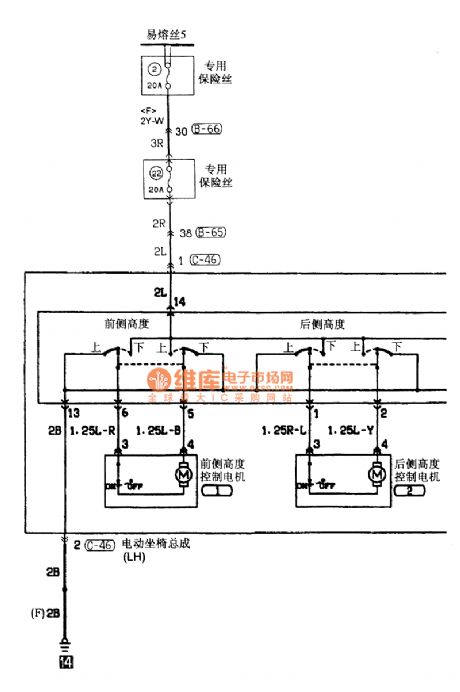
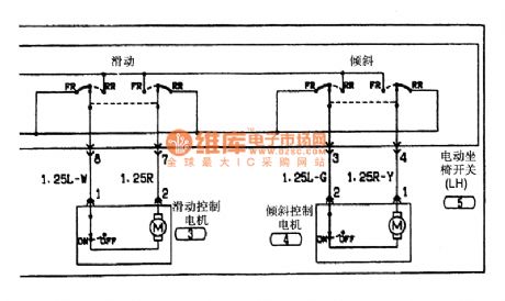
Southeast Ling Sheng power seat electric system circuit
Published:2011/7/20 21:51:00 Author:leo | Keyword: Power seat, electric system
View full Circuit Diagram | Comments | Reading(447)
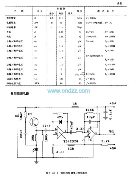
TDA2320 (TV) infrared remote control receiving preamplifier circuit
Published:2011/7/21 4:16:00 Author:TaoXi | Keyword: TV, infrared, remote control, receiving, preamplifier circuit
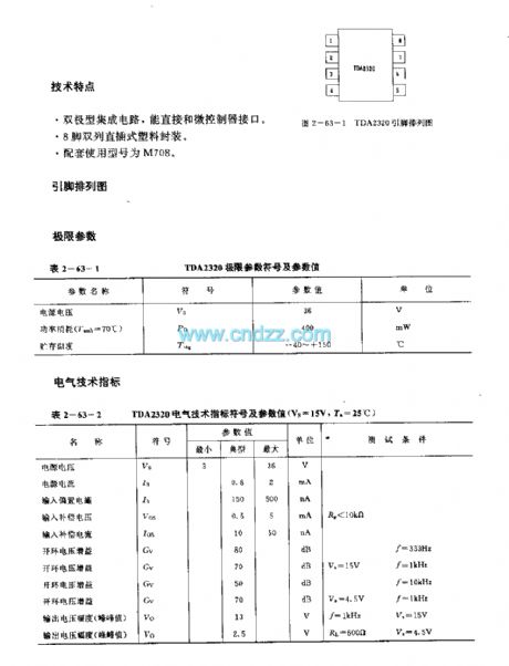
Features
This bipolar type integrated circuit can connected with the micro-controller directly.The 8-pin dual-row DIP plastic package.The matching model is M708.
(View)
View full Circuit Diagram | Comments | Reading(1015)
IX0986CE (video tape recorder) infrared remote control receiving preamplifier circuit
Published:2011/7/21 1:29:00 Author:TaoXi | Keyword: video tape recorder, infrared, remote control, receiving, preamplifier circuit
The IX0986CE has the same features, pin arrangement, pin functions, absolute maximum ratings, electrical specifications, logic diagram and the typical applications with the CX20106A, so they can directly exchange. (View)
View full Circuit Diagram | Comments | Reading(429)
IX0310PA (video tape recorder) infrared remote control receiving preamplifier circuit
Published:2011/7/21 1:28:00 Author:TaoXi | Keyword: video tape recorder, infrared, remote control, receiving, preamplifier circuit
The IX0310PA has the same features, pin arrangement, pin functions, absolute maximum ratings, electrical specifications, logic diagram and the typical applications with the uPC1373H, so they can directly exchange. (View)
View full Circuit Diagram | Comments | Reading(452)
lX0130CE (TV and audio equipment) 30 functions infrared remote control launch circuit
Published:2011/7/21 1:35:00 Author:TaoXi | Keyword: TV, audio equipment, 30 functions, infrared, remote control, launch circuit
The lX0130CE has the same features, pin arrangement, pin functions, absolute maximum ratings, electrical specifications, logic diagram and the typical applications with the M58484P, so they can directly exchange. (View)
View full Circuit Diagram | Comments | Reading(443)
CD114CP (sound equipment and FM receiver) FM intermediate frequency amplifier circuit
Published:2011/7/20 21:48:00 Author:TaoXi | Keyword: sound equipment, FM receiver, FM, intermediate frequency, amplifier circuit
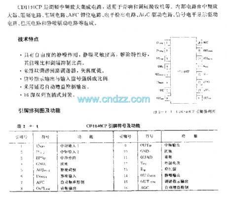
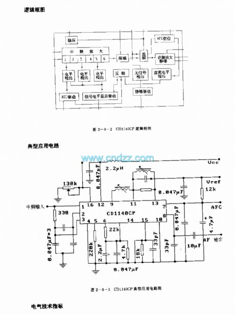
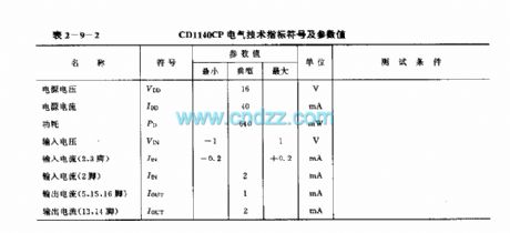
The CD114CP is designed as one kind of FM intermediate frequency amplifier circuit that can be used in the sound equipment and FM receiver. The internal circuit is composed of the intermediate frequency amplifier, the amplitude limiting circuit, the frequency discriminating circuit, the AFC clamping circuit, the level detection circuit, the AGC driving circuit, the signal level display driver circuit, the voltage stabilization circuit and the squelch circuit.
Features
It has the squelch function, the squelch sensitivity is high, the good contact characteristics, the high signal-to-noise ratio and AM rejection ratio.It uses the double-tuned loop tuner, the distortion degree is low.The signal indication output is proportional to the input signal.It uses the delay automatic gain control output.16-pin dual-row DIP package.
(View)
View full Circuit Diagram | Comments | Reading(820)
CA3035/CA3035V1 (TV) ultrasonic remote control receiving amplifier circuit
Published:2011/7/21 1:16:00 Author:TaoXi | Keyword: TV, ultrasonic, remote control, receiving, amplifier circuit
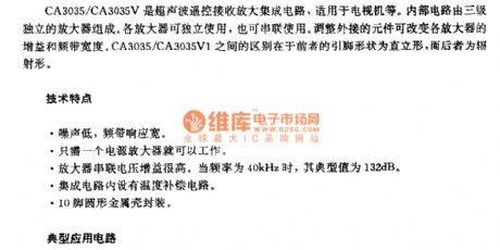

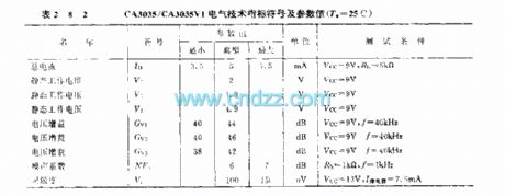
The CA3035/CA3035V1 is designed as one kind of ultrasonic remote control receiving amplifier circuit that can be used in the TVs. The internal circuit is composed of the three-stage independent amplifier. Every amplifier can be used independently, also can be used in tandem. You can change the gain and bandwidth by changing the external components. The difference between the CA3035 and CA3035V1 is that the CA3035's pin shape is upright type, the CA3035V1's pin shape is radiation type.
Features
Low noise, the frequency response is wide.Only one power amplifier.The amplifier series voltage gain is high.When the frequency is 40kHz, the typical value is 132dB.The circuit has the temperature compensation circuit.The 10-pin round metal shell package.
(View)
View full Circuit Diagram | Comments | Reading(1447)
1X0614CE (video tape recorder) infrared remote control receiving preamplifier circuit
Published:2011/7/21 1:24:00 Author:TaoXi | Keyword: video tape recorder, infrared, remote control, receiving, preamplifier circuit
The 1X0614CE has the same features, pin arrangement, pin functions, absolute maximum ratings, electrical specifications, logic diagram and the typical applications with the CX20106, so they can directly exchange. (View)
View full Circuit Diagram | Comments | Reading(471)
UPCI373H/HA (TV and video tape recorder) infrared remote control receiving preamplifier circuit
Published:2011/7/21 1:58:00 Author:TaoXi | Keyword: TV, video tape recorder, infrared, remote control, receiving, preamplifier circuit
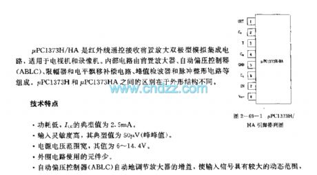

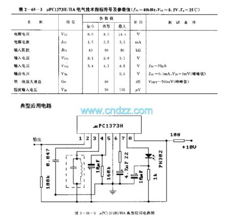
The uPC1373H/HA is designed as the infrared remote control receiving preamplifier bipolar type analog circuit that can be used in the TV and video tape recorder. The internal circuit is composed of the preamplifier, the automatic bias controller (ABLC), the limiter and the level drift compensation circuit, the peak detector, the pulse shaping circuit. The uPC1373H and uPC1373HA have the different shape structure. Features
Low power consumption, the typical value of Icc is 2.5mA.The input sensitivity is high, the typical value is 50uV (peak value).The power voltage range is wide, he value is 6-14.4V.The few external components.The automatic bias controller (ABLC) adjusts the gain of the amplifier automatically, and makes the input signal has the wide dynamic range.
(View)
View full Circuit Diagram | Comments | Reading(1266)
μPCI473H/HA (video recorder and TV set) infrared remote control receiving preamplifier circuit
Published:2011/7/21 3:21:00 Author:TaoXi | Keyword: video recorder, TV set, infrared, remote control, receiving, preamplifier circuit
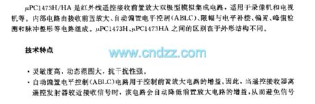
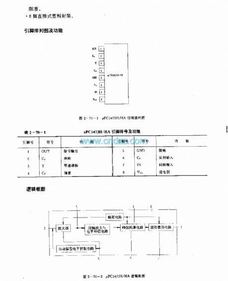
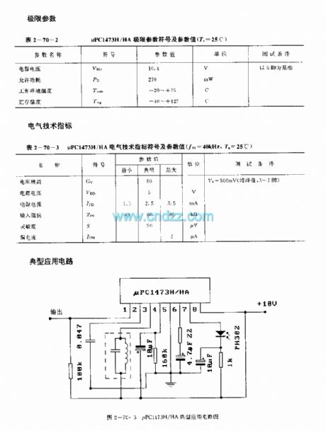
The μPCI473H/HA is designed as one kind of infrared remote control receiving preamplifier bipolar type analog circuit, and it can be used in the video recorder and TV set applications. The internal circuit is composed of the receiving preamplifier circuit, the automatic level control (ABLC) circuit, the amplitude limiting and level compensation, bias, peak value detection and pulse shaping circuit. The μPCI473H and μPCI473HA have the different shape structure.
Features
The high sensitivity, wide dynamic range and strong anti-interference performance.The automatic level control (ABLC) circuit can be used to control the gain of the preamplifier circuit. The 8-pin DIP plastic package.
(View)
View full Circuit Diagram | Comments | Reading(480)
Southeast Ling Sheng audio(VCD) electric system circuit
Published:2011/7/20 21:26:00 Author:leo | Keyword: Audio(VCD), electric system
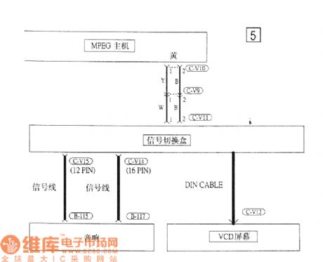
View full Circuit Diagram | Comments | Reading(717)
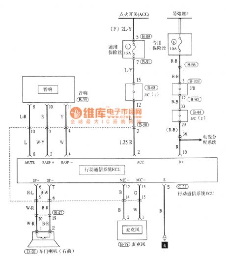
Southeast Ling Sheng audio electric system circuit
Published:2011/7/20 21:28:00 Author:leo | Keyword: Audio, electric system
View full Circuit Diagram | Comments | Reading(639)
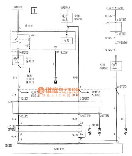
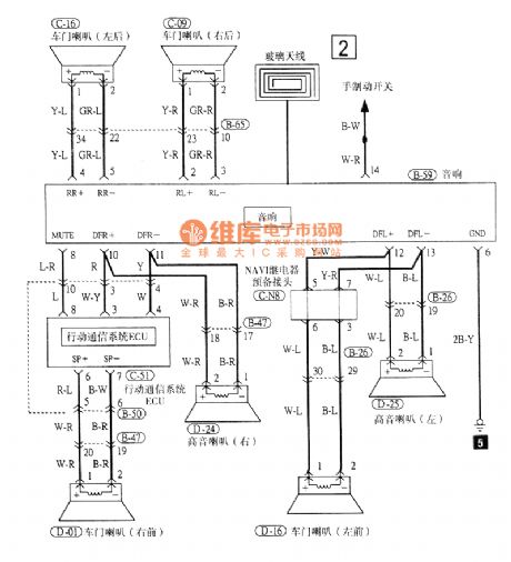
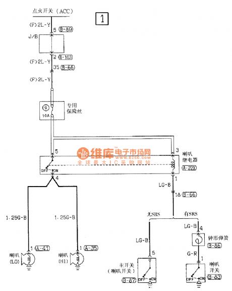
Southeast Ling Sheng speaker electric system circuit
Published:2011/7/20 21:32:00 Author:leo | Keyword: Speaker, electric system
View full Circuit Diagram | Comments | Reading(601)
μPC1099 internal equivalent circuit
Published:2011/7/11 2:34:00 Author:chopper | Keyword: internal, equivalent circuit
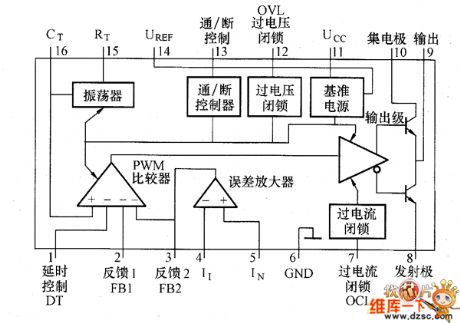
Figure shows the μPC1099 internal equivalent circuit.It consists of the reference power PWM comparator,oscillator,output pole,on/off control,over-voltage and over-current atresia part and the error amplifier.Reference power is to offer the circuits in chip the stable 5V voltage,moreover,external components will be set the maximum duty ratio,and it should be used in a feedback circuit with optical coupler.It is very important in practical application.
(View)
View full Circuit Diagram | Comments | Reading(583)
| Pages:173/250 At 20161162163164165166167168169170171172173174175176177178179180Under 20 |
Circuit Categories
power supply circuit
Amplifier Circuit
Basic Circuit
LED and Light Circuit
Sensor Circuit
Signal Processing
Electrical Equipment Circuit
Control Circuit
Remote Control Circuit
A/D-D/A Converter Circuit
Audio Circuit
Measuring and Test Circuit
Communication Circuit
Computer-Related Circuit
555 Circuit
Automotive Circuit
Repairing Circuit