
Index 165
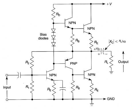
BASIC_QUASI_COMPLEMENTARY_POWER_AMPLIFIER_CIRCUIT
Published:2009/6/19 1:51:00 Author:May
View full Circuit Diagram | Comments | Reading(919)
RIAA_PHONO_AMPLIFIER
Published:2009/6/19 1:48:00 Author:May
View full Circuit Diagram | Comments | Reading(663)
ONE_CHIP_STEREO_PREAMP_WITH_TONE_CONTROL
Published:2009/6/19 1:48:00 Author:May

A Motorola TCA5500 or TCA5550 can provide a stereo preamplifier system with tone controls. This circuit provides a gain of about 10X, a 14-dB tone-control range, a 75-dB volume control range, and it can operate from 8 to 18 Vdc. IC2 provides 15 V for 101, and the input of IC2 can be supplied from the power amplifier's power supply (+) rail. D1 and R5 should be used if over 30 V input will be used. (View)
View full Circuit Diagram | Comments | Reading(4051)
BASIC_QUASI_COMPLEMENTARY_POWER_AMPLIFIER_WITH_SPLIT_POWER_SUPPLIES
Published:2009/6/19 1:47:00 Author:May
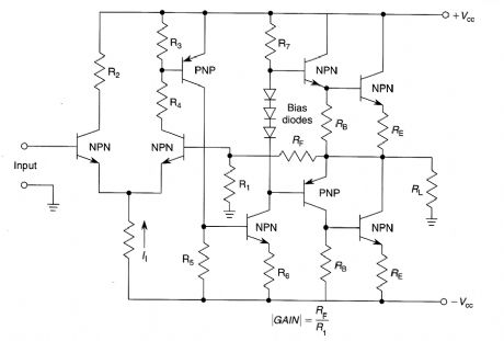
This is the basic circuit used in many audio power output stages where split supplies are used.This amplifier is inherently dc coupled and has high open loop gain and good dc stability if the feedback network is properly designed. (View)
View full Circuit Diagram | Comments | Reading(1206)
RFI_PROOF_AUDIO_POWER_AMPLIFIER
Published:2009/6/19 1:46:00 Author:May
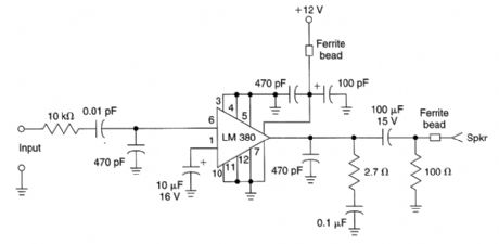
This 1-watt audio amplifier was used in an FM repeater and proved to be immune to strong RE signal pickup. It functioned well in very strong RE fields. (View)
View full Circuit Diagram | Comments | Reading(735)
16_W_BRIDGE_AMPLIFIER
Published:2009/6/19 1:45:00 Author:May

This circuit delivers 16 W RMS audio into a 4-Ωload (RL). The ICs are LM383s. (View)
View full Circuit Diagram | Comments | Reading(733)
POWER_SUPPLY_FOR_VACUUM_TUBE_AMPLIFIER
Published:2009/6/19 1:43:00 Author:May
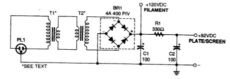
The power supply for the amplifier uses two low-voltage transformers connected back-to-back The full-wave bridge rectifier, BR1 provides dc for the filaments, plates, and screens. (View)
View full Circuit Diagram | Comments | Reading(953)
SIMPLE_VACUUM_TUBE_AMPLIFIER
Published:2009/6/19 1:43:00 Author:May
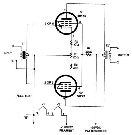
Using a pair of 60 FX5 tubes, direct operation from 120 Vac is possible. However, the use of a power supply with an isolation transformer is recommended. RI is adjusted for equal voltages at pin 1 of V1 and V2. The power output is about 2 to 3 watts. (View)
View full Circuit Diagram | Comments | Reading(1707)
LINE_OPERATED_AUDIO_AMPLIFIER
Published:2009/6/19 1:41:00 Author:May
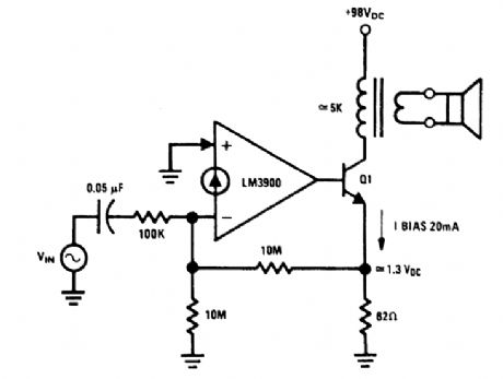
An audio amplifier which operates off a +98-Vdc power supply (the rectified line voltage) is of-ten used in consumer products. The external high-voltage transistor, Q1, is biased and controlled by the LM3900. The magnitude of the dc biasing voltage, which appears across the emitter resistor of Q1 is controlled by the resistor. The resistor is placed from the (-) input to ground. (View)
View full Circuit Diagram | Comments | Reading(806)
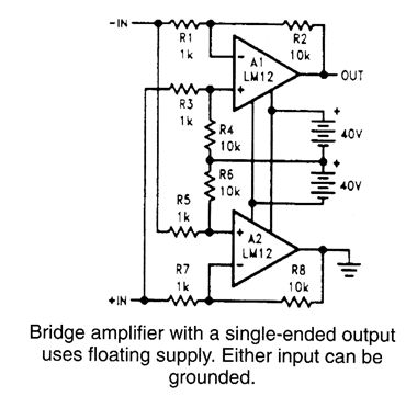
POWER_BRIDGE_AMPLIFIER_WITH_SINGLE_ENDED_OUTPUT
Published:2009/6/19 1:40:00 Author:May
View full Circuit Diagram | Comments | Reading(765)
10_WATT_AUDIO_AMPLIFIER
Published:2009/6/19 1:39:00 Author:May

This circuit is a general-purpose 10-W audio amplifier for moderate-power PA or modulator use in an AM transmitter. With higher voltages and a change in bias resistors, up to 30 W can be obtained. (View)
View full Circuit Diagram | Comments | Reading(1240)
PARALLEL_POWER_op_AMPS
Published:2009/6/19 1:37:00 Author:May
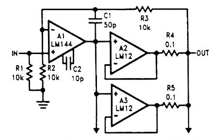
The power amplifiers, A2 and A3, are wired as followers and connected in parallel with the outputs coupled through equalization resistors. (View)
View full Circuit Diagram | Comments | Reading(1039)
AUDIO_POWER_AMPLIFIER,15W,12V
Published:2009/6/19 Author:May
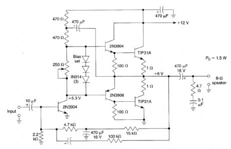
Although ICs have largely replaced circuits such as this, this circuit still finds use where the flexibil-ity of a discrete device design is desirable. Parts are easy to obtain and the problem of IC obsoles-cence is eliminated. The TIP31A can be heatsinked to a small metal heatsink, if desired. (View)
View full Circuit Diagram | Comments | Reading(1069)
ELECTRONIC_EAR_LOW_NOISE_AUDIO_AMPLIFIER_FOR_PAROBOLIC_DISH_MIKES
Published:2009/6/18 23:57:00 Author:May

Use this circuit with a parabolic reflector microphone for eavesdropping on distant sounds. (View)
View full Circuit Diagram | Comments | Reading(1822)
RIAA_PREAMPLIFIER
Published:2009/6/18 23:55:00 Author:May
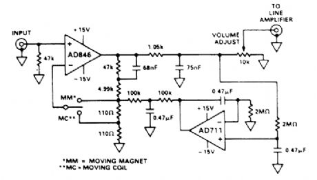
This preamp for RIAA phone use uses two op amps by Analog Devices. A switch selects compensation for moving magnet or rrtoving coil pickups. (View)
View full Circuit Diagram | Comments | Reading(2837)
SIMPLE_HIGH_GAIN_AUDIO_AMPLIFIER
Published:2009/6/18 23:53:00 Author:May
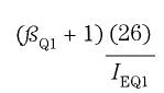
This amplifier has a very high gain in the audio range and is approximately the product of the current gains of the three transistors multiplied by the ratio of RL to (RIN+RS).RIN is approximately to: (View)
View full Circuit Diagram | Comments | Reading(1018)
FET_PHONO_CARTRIDGE_PREAMP
Published:2009/6/18 23:51:00 Author:May
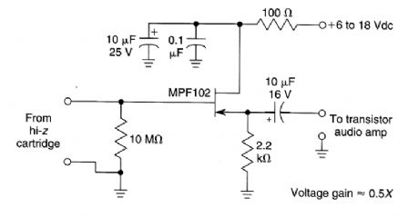
A high-Z phono cartridge can be rnatched to a low-Z amplifier with this circuit. The FET provides a current gain of over 1000x and a voltage gain of about 0.5x. (View)
View full Circuit Diagram | Comments | Reading(868)
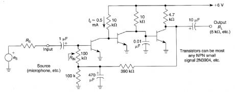
HIGH_GAIN_DYNAMIC_MICROPHONE_PREAMPLIFIER
Published:2009/6/18 23:50:00 Author:May

This microphone preamplifier is capable of about 70 dB or more gain at audio frequencies. Its gain is approximately equal to the product of the hfe of both transistors times the ratio of the load resistance to the input resistance of the preamp. As an approximation, these resistances are usually similar in value (≈2 to 5 kΩ) for most applications, so this ratio can be taken as unity. (View)
View full Circuit Diagram | Comments | Reading(1576)
SIMPLE_20_dB_GAIN_AUDIO_AMPLIFIER
Published:2009/6/18 23:49:00 Author:May

View full Circuit Diagram | Comments | Reading(1407)
LOW_LEVEL_AUDIO_AMPLIFIER
Published:2009/6/18 23:48:00 Author:May

View full Circuit Diagram | Comments | Reading(803)
| Pages:165/250 At 20161162163164165166167168169170171172173174175176177178179180Under 20 |
Circuit Categories
power supply circuit
Amplifier Circuit
Basic Circuit
LED and Light Circuit
Sensor Circuit
Signal Processing
Electrical Equipment Circuit
Control Circuit
Remote Control Circuit
A/D-D/A Converter Circuit
Audio Circuit
Measuring and Test Circuit
Communication Circuit
Computer-Related Circuit
555 Circuit
Automotive Circuit
Repairing Circuit