
Index 181
YDS-105-S2 basic application circuit
Published:2011/7/8 20:34:00 Author:chopper | Keyword: basic, application circuit

YDS-105-S2 basic application circuit is shown as picture
(View)
View full Circuit Diagram | Comments | Reading(1048)
grid drive circuit and full bridge output circuit
Published:2011/7/8 21:00:00 Author:chopper | Keyword: grid drive, full bridge, output circuit
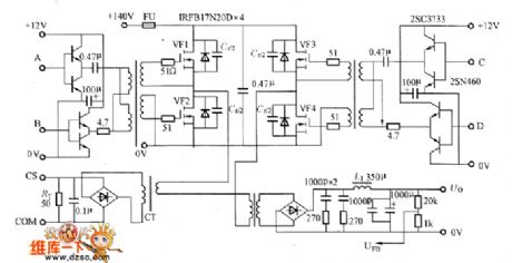
Figure shows the grid drive circuit andfull bridge output circuit.As for the phase shift type PWM circuit,duty ratio of grid drive wave is always 50%,so it is very easy to use pulse transformer in the drive circuit.
(View)
View full Circuit Diagram | Comments | Reading(729)
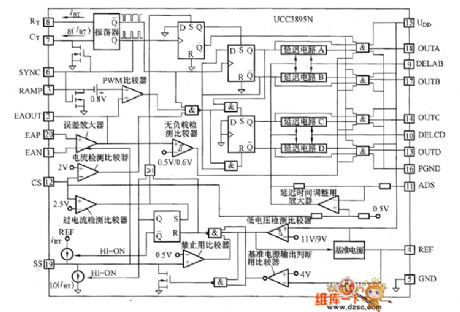
UCC3895N internal equivalent circuit
Published:2011/7/8 21:09:00 Author:chopper | Keyword: internal, equivalent circuit
View full Circuit Diagram | Comments | Reading(956)
SI-8000S inner equivalent circuit
Published:2011/7/8 6:12:00 Author:chopper | Keyword: inner, equivalent circuit
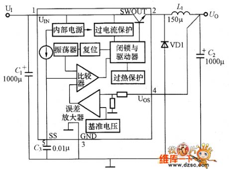
SI-8000S inner equivalent circuit is shown as picture
(View)
View full Circuit Diagram | Comments | Reading(714)
Practical digital amplifier (TL084) circuit
Published:2011/7/6 5:42:00 Author:chopper | Keyword: Practical, digital amplifier
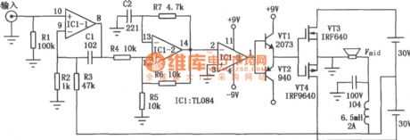
Conventional home theater digital amplifier requires the special integrated circuit, but such a integrated circuit has few manufacturers,and the high price. The circuit can be made by common components, and power is 50W.There is no power consumption when it is no-load,full load efficiency is about 85%,thus it has a certain practical value.However,the final stage of its power supply adopts floating ground ,the electromagnetic compatibility of the circuit is poor. As the 200kHz carrier does not filter out cleanly, its distortion and the signal to noise ratio and other indicators are still to be improved. (View)
View full Circuit Diagram | Comments | Reading(7534)
multimedia Hi-Fi power amplifier circuit
Published:2011/7/5 6:36:00 Author:chopper | Keyword: multimedia, Hi-Fi, power amplifier circuit
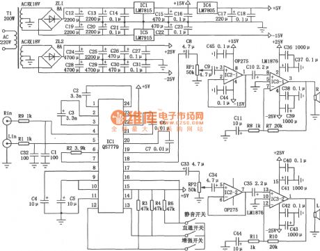
This circuit is a active power amplifier to listen Hi-Fi music on a PC, as picture shown. Audio processing chip ICl adopts uniwafer QS7779 virtual surrounding circuit produced by Canadian QSOUND company.Because the circuit includes Dolby prologic and Dolby digital mixed signal decoder,thus,first,it can improve the normal stereo signal effect;second, when it plays a DVD Dolby digital signal,it can be decoded firstly, then the matrix computing, virtualization before outputting from the two-channel; three,it can present different effects by switch.
(View)
View full Circuit Diagram | Comments | Reading(4825)
Air-conditioning Circuit One of Southeast LingShuai Cars
Published:2011/7/7 21:16:00 Author:Michel | Keyword: LingShuai Cars, Air-conditioning Circuit One
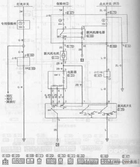
Air-conditioning Circuit of Southeast LingShuai Cars (View)
View full Circuit Diagram | Comments | Reading(684)
μA741 direct coupling audio power amplifition circuit
Published:2011/7/7 1:15:00 Author:chopper | Keyword: direct, coupling, audio power, amplifition
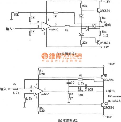
The picture shows direct coupling audio power amplifition circuit.It has two pratical methods of audio power amplifier formed by integrated op-amp.The first practical form is shown in (a).And the structure of the circuit is to add the complementary symmetry emitter follower to the output end of op-amp, and this form is simple,easy to use,but power usage is low.Figure (a) tells that the emitters of two dynatrons are connected with RE (1.2Ω) in series, whose role is to implement over-current protection to power amplifier dynatron. (View)
View full Circuit Diagram | Comments | Reading(1551)
AE1169-Equipped Enhanced Code Lock Circuit
Published:2011/6/30 4:18:00 Author:Joyce | Keyword: AE1169-Equipped, Enhanced, Code Lock
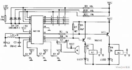
When the button of an AE1168-equipped enhanced code lock is pressed, AE1168 will locate the corresponding button through keyboard scan. And it will control alarm relay K1, relay K2 after being analysed by internal logic according to the state of S1, S2, S3.The circuit uses 12-bit keyboard with the * key signifying confirmation ; the # key signifying clear.Tf oneinputs the wrong password out of carelessness,as long as the * key has not been pressed, one can clickthe button # to clear the wrong code. By switching S1, S2, S3 , we can confirm collectively or by oneself. (View)
View full Circuit Diagram | Comments | Reading(810)
musical E-bell circuit
Published:2011/6/12 21:36:00 Author:chopper | Keyword: musical E-bell
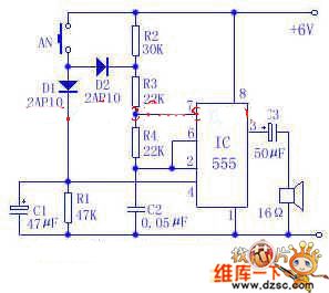
The following picture is a circuit of doorbell which can send out a sound like ding,dong .It is constituted of a time-base circuit integrated package and peripheral cells.The bell has a graceful and vivid tone,and it is easy and cheap to set up .A 6V laminated battery can be used over 3 months.Its electric power consumption is very low.The IC in the picture is time-base circuit integrated package 555 which forms astable multivibrator.Press the AN(which is set up on the door),the oscillator works, and the oscillating frequency is about 700Hz,and the speaker sends out ding .
(View)
View full Circuit Diagram | Comments | Reading(1923)
The High confidentiality electronic lock circuits T630 and T631
Published:2011/6/14 2:50:00 Author:TaoXi | Keyword: High confidentiality, electronic lock
You can use the jump yard decoding circuit to form the high confidentiality electronic lock that can be used in the safety deposit box, the confidential file cabinet, the confidential room applications to ensure their safety. The high confidentiality electronic lock circuit which is composed of the jump yards decoding circuit (ACM1330E/ACM1550D) and the long-wave remote control transmitter / receiver circuit (T630/T631) is as shown in the figure. (a) is the coded excitation circuit; (b) is the receiving decoder circuit.
(View)
View full Circuit Diagram | Comments | Reading(802)
Modem and PC interface circuit
Published:2011/7/8 5:52:00 Author:TaoXi | Keyword: Modem, PC, interface circuit
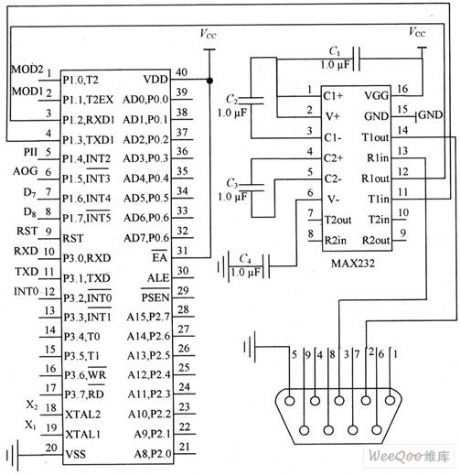
The Modem and PC interface is the interface circuit of the Modem's single-chip microcomputer W77E58 and the PC, the W77E58 supports the TTL level, and the microcomputer serial communication interface RS 232C supports the EIA level, so you need to design the level conversion circuit when you are realizing the serial communication between them to meet their needs.
The level conversion circuit is the interface circuit of the command center modem and the microcomputer, it is also a part of the wireless data transmission system hardware circuit (command center).
(View)
View full Circuit Diagram | Comments | Reading(935)
Electronic Thermometer of Transistor Temperature Sensor
Published:2011/7/10 5:24:00 Author:Michel | Keyword: Transistor Temperature Sensor, Electronic Thermometer
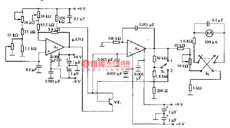
The figure is electronic thermometer of the transistor temperature sensor.In the circuit VT1 is the transistor temperature sensor and its measuring range is -30一100℃.The circuit is composed of DC amplifier and benchmark voltage circuit, Al constitutes benchmark voltage circuit and A2 constitutes DC amplifier. S1 is used for temperature measuring range and it's 0一100℃ when 1 is swithced and it's 0一5℃ when 2 is switched.S2 is used for the header polarity switch. (View)
View full Circuit Diagram | Comments | Reading(1482)
PWM Brightness Adjusting Circuit
Published:2011/6/28 1:59:00 Author:Michel | Keyword: PWM Brightness, Adjusting Circuit
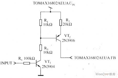
R1 and R2 are used to adjust to 29V.This is very useful when output end occurres incident opening.Output division voltage may rise ,which causes devices damage if there is division voltage devices.C1 and R5 are used to stablize voltage feedback loop.
The best way to control white LED brightness is to adjust white LED via a low frequency PWM pulse.The low frequency PWM pulse modulation method can make the white LED current keep stable current scale according to dutyfactor change and it can make LED light wavelengths keep constant in the adjustment range.PWM adjusting brightness circuit is shown as the aboved figure.
Picture:PWM Brightness Adjusting Circuit (View)
View full Circuit Diagram | Comments | Reading(792)
Enhanced RS-485 interface with isolation circuit
Published:2011/7/7 7:21:00 Author:Fiona | Keyword: Enhanced interface, with isolation
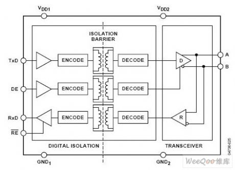
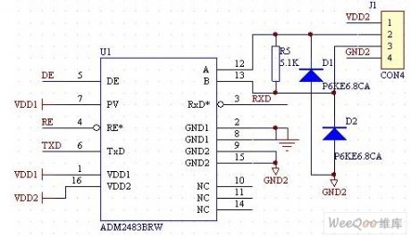
ADM2483 is enhanced RS-485 transceiver with isolation, the internal block diagram is shown as Figure 1,which includes a three-channel isolator,a differential drive with three-state output and a differential receiver with three-state input.The receiver with 1 / 8 unit load inputs impedance that allows more than 256 transceivers to access bus, the highest transfer rate is 500Kbps. Logical end is compatible with 3V/5V power supply, the bus terminal has 5V power supply.Compared with other RS-485 interface chips,ADM2483 integrates the magnetic isolation technology,it only requires an external DC/DC power supply.
(View)
View full Circuit Diagram | Comments | Reading(2210)
The CAN total line interface circuit of vortex flowmeter
Published:2011/7/8 3:25:00 Author:Fiona | Keyword: The CAN total line interface, vortex flowmeter
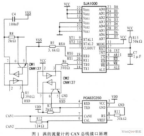
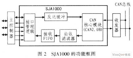
CAN total line is a serial data communication protocol,in CAN total line communication interface integrates the CAN protocol's the physical layer and data link layer,it can accomplish the process of framing to the communication data.The author is regard SJA1000 as Flowmeter's CAN controller,it is connected to the I/O of CPU(SCM) immediately so that it composes CAN total line of PCA82C250.This contruction is very easy to achieve sending and receiving information of CAN network nodes,thus achieves on-site control.SJA1000's AD0~AD7 is connected to MSP420F149's P0,INT is connectedto P1.0,/CS is connectedto P1.1,/RD is connected to P1.2,/WR is connected to P1.3,ALE is connected to P1.4,after being respectively connected through two high-speed optocoupler CNW137 and PCA82C250,TX0 and RX0 of SJA1000 are connected to the CAN total line.
(View)
View full Circuit Diagram | Comments | Reading(1340)
SCM and SJA1000 CAN controller interface circuit
Published:2011/7/8 3:30:00 Author:Fiona | Keyword: controller interface
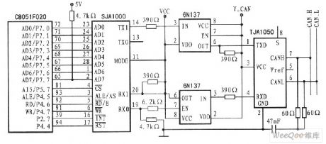
The picture shows the C8051F020 SCM and hardware connection circuit principle of SJA1000 controller.SJA1000 takes up 0x8000-0x80FF external RAM space.When SCM visits the above space,the chip select signal will select SJA1000. C8051F020 has high and low two external memory interfaces. Therefore,the AD0-AD7 of SJA1000 is connected to high port P7 of C8051F020, CS is connected to the chip select signal of external memory which the base address is 0x8000.When C8051F020 visits 0x8000-0x80FF,CPU can execute the corresponding read / write operations to SJA1000.RD,WR and ALE of SJA1000 are connected to corresponding pin of C8051F020,INT is connected to the INT0 pin of C8051F020,so that C8051F020 can visit SJA1000 through interrupt mode.
(View)
View full Circuit Diagram | Comments | Reading(3592)
MC34011 voltage-stabilizing circuit
Published:2011/7/8 3:44:00 Author:Fiona | Keyword: voltage-stabilizing
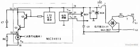
MC34011 voltage-stabilizing circuit is shown as above,NC34011 voltage-stabilizing circuit consists of a part of this chip,the external whole bridge,voltage regulator BG8 and other circuit. Its function is providing stable 1.1V DC voltage for the MC34011 working,the stable DC voltage is sent to 3,4 pins of MC34011 by the emitter of BG9.
(View)
View full Circuit Diagram | Comments | Reading(1231)
MC34011 ringing circuit
Published:2011/7/8 3:57:00 Author:Fiona | Keyword: ringing
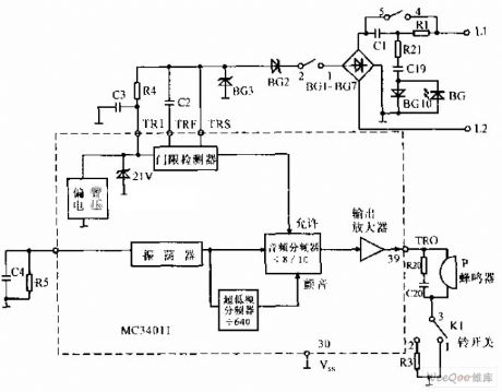
MC34011 ringing circuit is shown as above,the carrier ring signal sent by L1,L2 is sent into the ringing signal processing circuit of MC3401 after the bridge rectifying(threshold detection,comparison frequency division,output amplification, etc.).The ring signal is sent out from 39 pin to the buzzer.The loudness of the buzzer is controlled by K1 switch,when K1 is set at 1 ,the buzzer rings;when K1 is set at 2 ,the buzzer is light.
(View)
View full Circuit Diagram | Comments | Reading(837)
TEA1062 talking circuit
Published:2011/7/8 4:07:00 Author:Fiona | Keyword: talking
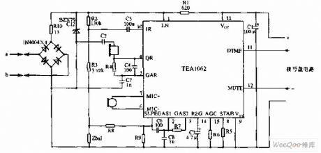
TEA1062 talking circuit is shown as above,TEA1062 is bipolar integrated circuit produced by Philips company,it can complete the voice access,the line interface and the dial interface functions,dialing and talking use electronic conversion,low call uses electronic conversion,there is as low as 1.6V DC line voltage to adapt to many parallel machines.The figure is typical application in the phone.
(View)
View full Circuit Diagram | Comments | Reading(4543)
| Pages:181/250 At 20181182183184185186187188189190191192193194195196197198199200Under 20 |
Circuit Categories
power supply circuit
Amplifier Circuit
Basic Circuit
LED and Light Circuit
Sensor Circuit
Signal Processing
Electrical Equipment Circuit
Control Circuit
Remote Control Circuit
A/D-D/A Converter Circuit
Audio Circuit
Measuring and Test Circuit
Communication Circuit
Computer-Related Circuit
555 Circuit
Automotive Circuit
Repairing Circuit