
Index 198
QS6M4 internal circuit
Published:2011/6/13 19:39:00 Author:John
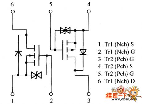
QS6M4 internal circuit is shown below.
(View)
View full Circuit Diagram | Comments | Reading(568)
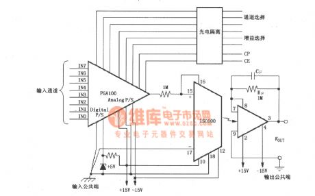
The multi-channel separation programmable amplifier of the data collecting system composed of IS0100
Published:2011/6/15 20:17:00 Author:Borg | Keyword: multi-channel, programmable amplifier, data collecting system
View full Circuit Diagram | Comments | Reading(588)
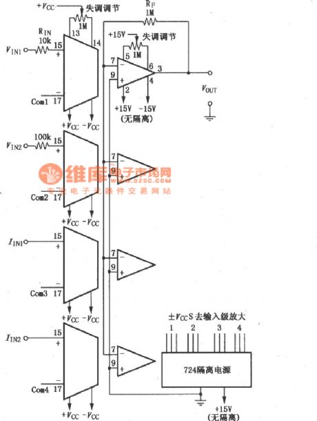
The 4-channel separation amplifier composed of 4 ISO100
Published:2011/6/15 20:35:00 Author:Borg | Keyword: 4-channel, separation amplifier
View full Circuit Diagram | Comments | Reading(615)
The STK4171 application circuit
Published:2011/6/19 10:27:00 Author:Seven | Keyword: application circuit
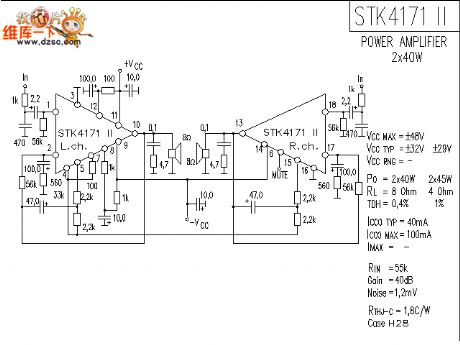
The STK4171 application circuit is shown as follows:
(View)
View full Circuit Diagram | Comments | Reading(3669)
CNY44 analog isolation circuit
Published:2011/6/11 1:37:00 Author:chopper | Keyword: analog, isolation
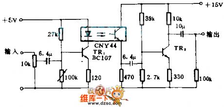
This circuit can be used when the analog signals is transmitted among equipment of different earth potential.The 3 dB bandwidth of the circuit is between 6HZ and 80KHZ,and between 100KHZ and 20KHZ,the total harmonic distortion is less than 1.5% when +8V(peak-peak) outputs power Level.
(View)
View full Circuit Diagram | Comments | Reading(1693)
MN1874033TNW--the single chip microcomputer integrated circuit
Published:2011/6/11 5:19:00 Author:qqtang | Keyword: single chip microcomputer, integrated circuit
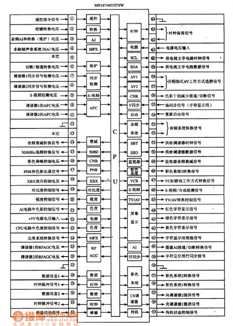

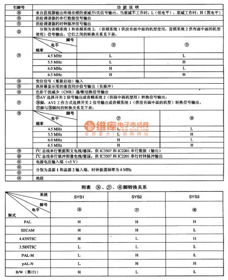
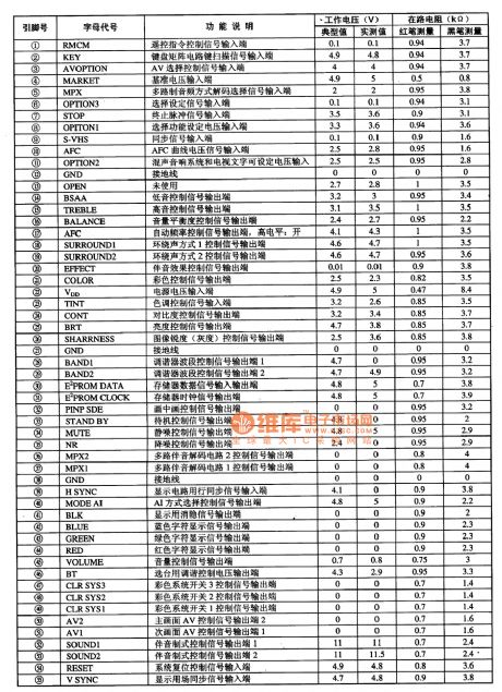
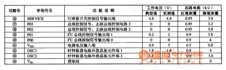
1. Function featuresMN1874033TNW consists of CPU, clock oscillating circuit, reset control circuit, I2C general control circuit, screen displayed letter generating and processing circuit, and other control and affiliated function circuits, etc.2.pin functions and data MN1874033TNW is in 64-pin dual line package, whose internal circuit, pin functions and signal flow is shown in the figure, and its pin function introduction is in the table.
The internal circuit, pin functions and signal flow of MN1874033TNW
(View)
View full Circuit Diagram | Comments | Reading(760)
MN1872432TWJ--the single chip microcomputer integrated circuit
Published:2011/6/11 5:27:00 Author:qqtang | Keyword: single chip microcomputer, integrated circuit

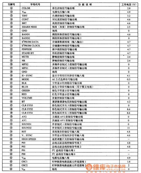
MN1872432TWJ is the single chip microcomputer integrated circuit produced by Panasonic, which is widely used in the large screen color TV sets of Panasonic cores.1.function featuresMN1872432TWJ consists of the CPU, clock oscillating circuit, reset control circuit, key order decoding circuit, displayed letter generating and processing circuit, and other control and affiliated function circuits, etc.2.pin functions and dataMN1872432TWJ is in 64-pin dual line package, whose pins are listed in the table.
(View)
View full Circuit Diagram | Comments | Reading(652)
MN1872432TWI--the single chip microcomputer integrated circuit
Published:2011/6/11 5:33:00 Author:qqtang | Keyword: single chip microcomputer, integrated circuit
MN1872432TWI is the single chip microcomputer integrated circuit produced by Panasonic, which is widely used in the large screen color TV sets of Panasonic cores.MN1872432TWI is in 64-pin dual in-line plastic package, whose pin functions and data are listed in the table.Pin functions and data of MN1872432TWI
(View)
View full Circuit Diagram | Comments | Reading(873)
MN1872419TKO--the single chip microcomputer integrated circuit
Published:2011/6/11 5:41:00 Author:qqtang | Keyword: single chip microcomputer, integrated circuit
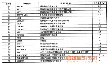
MN1872419TKO is the single chip microcomputer integrated circuit, which is widely used in the large screen color TV sets of Panasonic cores.1.function featuresIt consists of the signal process circuit, key order decoder, PIP control circuit, system control circuit,I2C general control circuit, standby/ starting up control circuit, display letter generating and processing circuit, and other control and affiliated function circuit, etc.2.pin functions and dataMN1872419TKO is in 64-pin dual line package.
(View)
View full Circuit Diagram | Comments | Reading(563)
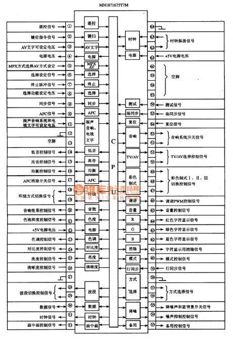
MN1871675T7W--the single chip microcomputer integrated circuit
Published:2011/6/11 8:55:00 Author:qqtang | Keyword: single chip microcomputer, integrated circuit
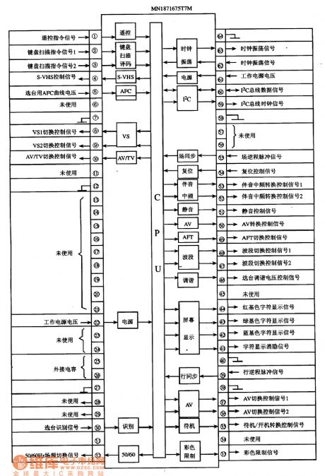
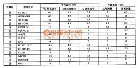

1.function introductionMN1871675T7M consists of the clock oscillating circuit, reset circuit, key scanning order decoding circuit, I2C general circuit, remote order signal process circuit, AV/TV converting control circuit, system converting control circuit, letter display circuit, standby/starting up alternating circuit and other affiliated function circuits, etc.2. Pin function and dataMN1871675T7W is in 64-pin dual in-line package, whose pin functions, internal circuit and signal flow are shown in the figure.
(View)
View full Circuit Diagram | Comments | Reading(965)
3.1 the amplifier circuit
Published:2011/6/15 3:32:00 Author:Borg | Keyword: amplifier circuit
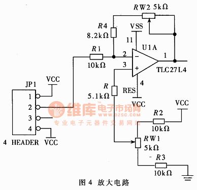
In figure 4 is the amplifier circuit in the signal adjusting circuit, which is a passive feedback amplifier circuit composed of the computing amplifier, and the amplified times of the output signals can be further trimmed by adjusting the adjustable resistor RW2. The output signal subtracts 0g LEV, which can make the output voltage value of the amplifier be 1/10 of the acceleration, so it is more convenient to indicate the number. By adjusting the resistance of RW2, the 0g LEV can be trimmed, and the signal bias can be modified. In the figure, VSS is a power supply of -5V, VCC is a +5V power supply.
(View)
View full Circuit Diagram | Comments | Reading(1047)
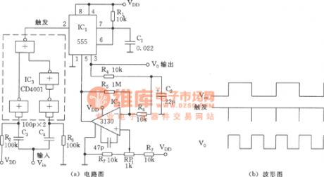
The frequency doubler of 50% duty cycle (555)
Published:2011/6/15 2:54:00 Author:Borg | Keyword: frequency doubler, duty cycle
View full Circuit Diagram | Comments | Reading(2119)
Haier FCD-40A horizontal electric water heater circuit
Published:2011/6/14 3:02:00 Author:Christina | Keyword: Haier, horizontal, electric water heater
Haier FCD-40A horizontal electric water heater circuit
(View)
View full Circuit Diagram | Comments | Reading(703)
51 monolithic burning device circuit
Published:2011/6/14 3:02:00 Author:Christina | Keyword: monolithic, burning device
51 monolithic burning device circuit
(View)
View full Circuit Diagram | Comments | Reading(517)
interface circuits of the MAX110/MAX111 and the SCM
Published:2011/6/13 4:21:00 Author:Christina | Keyword: SCM, interface circuit
View full Circuit Diagram | Comments | Reading(629)
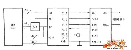
interface circuits of the MAX187/189 and 8031
Published:2011/6/13 4:20:00 Author:Christina | Keyword: interface circuit
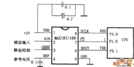
View full Circuit Diagram | Comments | Reading(693)
Use AT89C2051 microcontroller making steamed rice ark timer switch
Published:2011/5/22 8:19:00 Author:Crystal Liu | Keyword: AT89C2051 microcontroller making steamed rice ark timer switch, AT89C2051, 7805
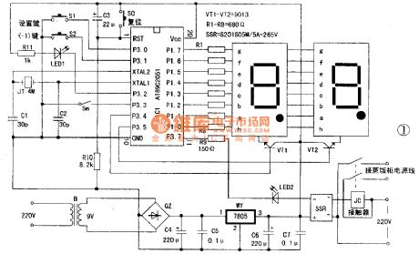
The circuit shows in figure 1.AT89C2051 single-chip microcomputer chip IC1 as the core of this circuit ,C3 and R10 formed simple automatic reset circuit.JT、 C1、C2 and ICl related pins formed SCM clock circuit.The display uses two share with anode type digital tube.15 I/O port of ICl all be used.Among them, the PI. 0 for seconds show lose exports,through a limited flow resistance of various digital tube connected to the decimal point electrode,during normal working,use decimal shining as seconds signal display ~P1.1-P1.7 as seven segment digital pipe section choose signal(Low-level effective) lose exports,through a limited flow resistance respectively ,connect the corresponding to the digital tube electrode.Digital pipe display dynamic scanning manner,it's dynamic bits choose signal respectively by IC P3.4 and P3.5 output ,high-level effective.
(View)
View full Circuit Diagram | Comments | Reading(5368)
Voice Compression Circuit Diagram formed by MC1590 and Others
Published:2011/6/14 20:48:00 Author:leo | Keyword: Voice Compression Circuit Diagram formed by MC1590 and Others, MC1590
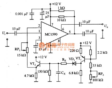
View full Circuit Diagram | Comments | Reading(3520)
Double MOS Memory Interface Circuit
Published:2011/5/18 9:43:00 Author:Joyce | Keyword: Double MOS, Memory , Interface
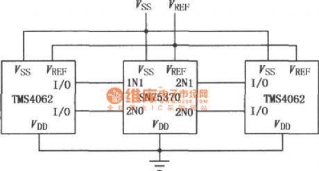
SN75370 is a monolithic integrated read/write interface circuit, which can be used as input/output interface in 4062 and in MOS RAM and TTL circuit of the same type. It can be connected directly with I/O interface of similar MOS RAM like 4062 . When it is written into operation, the drive can provide a complementary high voltage output with a high sensitive read operation.TTL will input with compatible diode clamp of DTL,and output with compatible data of DTL .The output endof data can act as AND connection. And the power supply has a extensive range. As shown in the figure is the interconnection graph of SN75370 and 4062. (View)
View full Circuit Diagram | Comments | Reading(634)
Meeting Timer Circuit
Published:2011/5/18 9:39:00 Author:Joyce | Keyword: Meeting, Timer
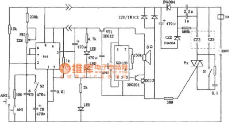
As shown in the figure the limited time of this circuit ranges from 5 minutes to 1 hour. PR1, C8 and C9 are the timing components. The sockets for 220V AC power supply,which controls the audio power amplifiers are CZ1 and CZ2. To press AN2, 555 means reset and start .Its feet ③ outputs high level, which will trigger the thyristor to make it breakover.And when CZ1 and CZ2 have voltage,the timing will begin. KD - 153 will produce sounds for a few seconds to indicate the circuit is proper.When the timer stops,feet 5553 will output low level,thus VS will turn off, and no voltage will be on CZ1 and CZ2.After hearing sounds produced by KD - 153 for a few seconds ,the limited time for the meeting is up.
The circuit is alsoapplicable for other control circuits which needs timing. (View)
View full Circuit Diagram | Comments | Reading(576)
| Pages:198/250 At 20181182183184185186187188189190191192193194195196197198199200Under 20 |
Circuit Categories
power supply circuit
Amplifier Circuit
Basic Circuit
LED and Light Circuit
Sensor Circuit
Signal Processing
Electrical Equipment Circuit
Control Circuit
Remote Control Circuit
A/D-D/A Converter Circuit
Audio Circuit
Measuring and Test Circuit
Communication Circuit
Computer-Related Circuit
555 Circuit
Automotive Circuit
Repairing Circuit