
Index 185
The Sound control electronic corsage circuit
Published:2011/6/15 1:44:00 Author:Christina | Keyword: Sound control, electronic corsage
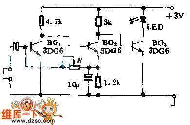
This circuit is composed of the sound source amplifier and the LED driving circuit. The microphone is used as the voice detector to change the voice signal into the electrical signal and this electrical signal is amplified by BG1 and BG2 to drive BG3 to turn on the LED.
(View)
View full Circuit Diagram | Comments | Reading(870)
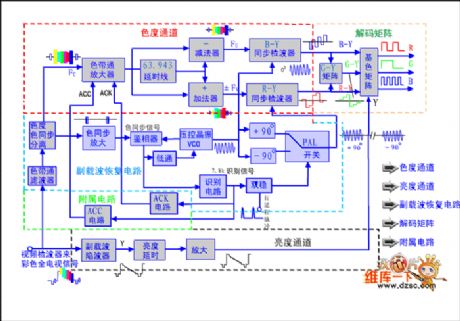
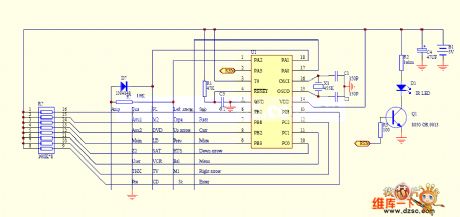
Standard PAL standard color decoder frame circuit
Published:2011/7/4 10:59:00 Author:John | Keyword: decoder
View full Circuit Diagram | Comments | Reading(1001)
The Differential amplifier circuit
Published:2011/6/15 1:44:00 Author:Christina | Keyword: Differential, amplifier
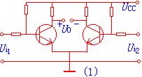
The basic form requirements of the circuit:
The parameters of the two circuits are completely symmetry. Also the temperature features of the two tubes are completely symmetry.
Working principle: when you input the signal Ui=0, the two tubes have the same current, also the collector electrode potential, so the output voltage Uo=UC1-UC2=0. When the temperature is increasing, the currents of the two tubes increase too, and the collector electrode potentials reduce, because they are in the same temperature environment, so the two tube have the same variation values of current and voltage, the output voltage is still zero. (View)
View full Circuit Diagram | Comments | Reading(725)
The OTL power amplifier circuit
Published:2011/6/15 1:44:00 Author:Christina | Keyword: OTL, power amplifier
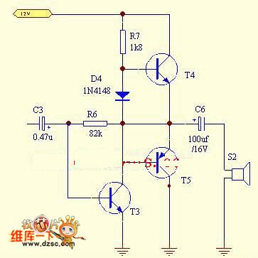
Figure: The OTL power amplifier circuit (View)
View full Circuit Diagram | Comments | Reading(2602)
The High-speed TTL probe circuit
Published:2011/6/15 1:43:00 Author:Christina | Keyword: High-speed, TTL, probe
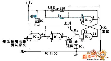
The RS flip-flop which is composed of the NAND gates can detect the narrow pulse, and the narrowest pulse width is the total delay time (about 30ns) of the flip-flop's two NAND gates. When the pulse appears, the circuit will change and the LEDs display the output state of flip-flop. You must use the K after detecting the pulse; By resetting the circuit and according to the choice of K1, this circuit can response the positive pulse or negative pulse.
(View)
View full Circuit Diagram | Comments | Reading(734)
The TIL probe circuit
Published:2011/6/15 1:43:00 Author:Christina | Keyword: TIL, probe

If the polarity switch is in the position as shown, so when the input probe receives the low-level (negative) pulse, the LED turns on until the circuit is reset. If you push switch to another position, and there is high-level voltage or +5V input pulse, the LED turns on too.
(View)
View full Circuit Diagram | Comments | Reading(751)
The Calendar Clock Circuit
Published:2011/6/15 1:43:00 Author:Christina | Keyword: Calendar, Clock
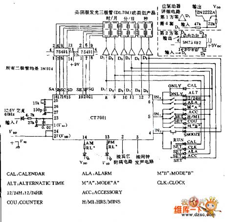
The FCM CT7001 clock chipis produced by the Fairchild company, and this device let the 6-digit & 7-segment LED display the time of 12h or 24h, and also has the function of 28/30/31 calendar and alarm. The (3)(5)(10)(12) of the SN74591 driver chip connect to (11) by a 150Ω resistor. Generally the RL is 2.7KΩ, it limits the LED current less than 5mA. (View)
View full Circuit Diagram | Comments | Reading(1777)
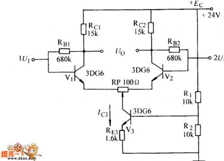
The Circuit Of Symmetry Amplifier
Published:2011/6/15 1:42:00 Author:Christina | Keyword: Symmetry Amplifier
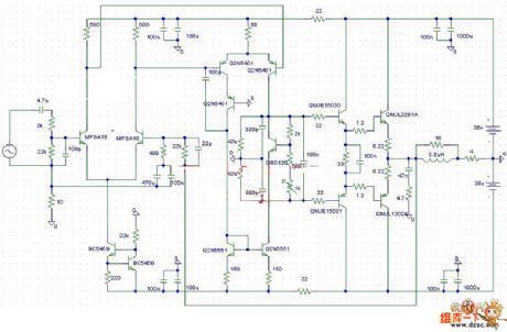
The Circuit Of Symmetry Amplifier is as shown.
Welcome to reprint, the information is from the Weiku Electronic Market Network (www.dzsc.com). (View)
View full Circuit Diagram | Comments | Reading(1340)
Op amp circuit diagram
Published:2011/6/24 2:43:00 Author:Ecco | Keyword: Op amp
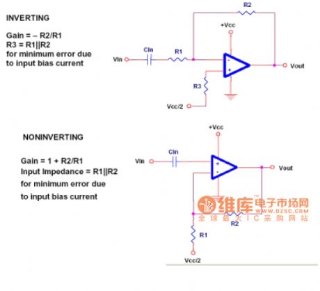
There are two basic types of amplifier circuits: noninverting amplifier and the inverting amplifier. Their AC-coupled version is shown in Fig. For AC circuits, reverse means that the phase angle is moved in 180 degrees. This circuit uses a coupling capacitor-Cin. Cin is used to prevent circuit DC amplification, so the circuit will only produce amplification oon AC. In the DC circuit, Cin is omitted, then it must be calculated on the DC amplification. In the high-frequency circuits, it is very important to violate the op amp's bandwidth limitations or not.
(View)
View full Circuit Diagram | Comments | Reading(1047)
Earphone Amplifying Circuit of OPA2134
Published:2011/6/24 2:24:00 Author:Michel | Keyword: Earphone, Amplifying Circuit
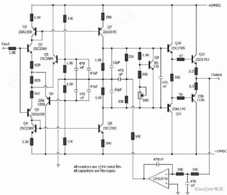
The circuit is composed of OPA2134 and triodes etc. (View)
View full Circuit Diagram | Comments | Reading(4907)
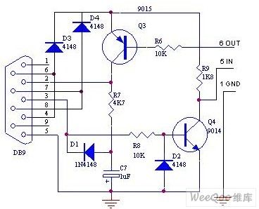
RS-232 serial interface circuit designed with two transistors
Published:2011/7/1 7:03:00 Author:Fiona | Keyword: serial interface, designed with two transistors
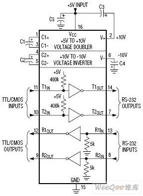
The above is the MAX232's internal circuit.
The below that I make is the 6688 data line circuit which uses transistor, capacitor C7 produces negative pressure:
(View)
View full Circuit Diagram | Comments | Reading(2575)
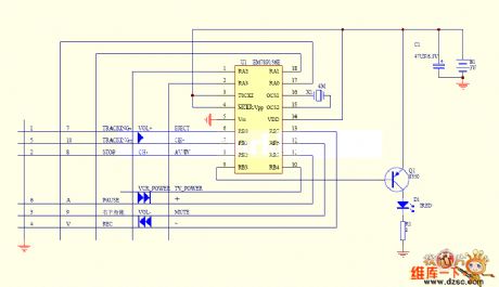
TV remote control 08 circuit
Published:2011/7/4 0:19:00 Author:John | Keyword: TV remote control
View full Circuit Diagram | Comments | Reading(726)
TV remote control 07 circuit
Published:2011/7/4 0:20:00 Author:John | Keyword: TV remote control
View full Circuit Diagram | Comments | Reading(800)
TV remote control 06 circuit
Published:2011/7/4 0:22:00 Author:John | Keyword: TV remote control
View full Circuit Diagram | Comments | Reading(700)
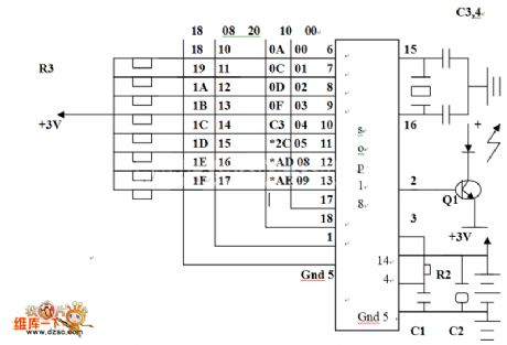
TV remote control 05 circuit
Published:2011/7/4 0:25:00 Author:John | Keyword: TV remote control
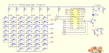
The resistance forresistors marked with * is optional within10k-100k, which is set aslarge as possible.
(View)
View full Circuit Diagram | Comments | Reading(759)
The amplifier circuit diagram for measuring small current
Published:2011/7/1 1:51:00 Author:Ecco | Keyword: amplifier , measuring, small current

View full Circuit Diagram | Comments | Reading(799)
Dark current negative feedback differential amplifier circuit diagram
Published:2011/7/1 1:56:00 Author:Ecco | Keyword: Dark current , negative feedback , differential amplifier
View full Circuit Diagram | Comments | Reading(1876)
The wide band AC separation amplifier circuit of photoelectric couplers
Published:2011/7/3 22:11:00 Author:Borg | Keyword: wide band, AC separation amplifier, photoelectric couplers
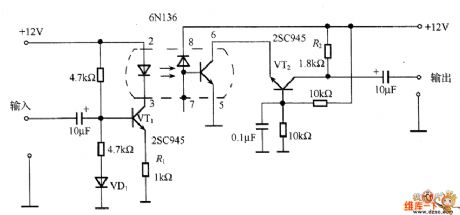
In th figure is the wide band AC separation amplifier circuit of photoelectric couplers. When there's no modulation, the photoelectric coupler must work with a DC bias current which is offered by VT1, VD1 is used to improve the temperature feature of VT1. In the circuit, the 6N136 photoelectric coupler is adopted, the LED of it outputs a very low current which is amplified by the transistor. To improve the frequency feature, the common pole circuit composed of TV2 converts the current into the voltage. The voltage gain is decided by the resistor R2 on the collecting electrode of VT2, the working point adjustment is decided by R1.
(View)
View full Circuit Diagram | Comments | Reading(921)
The singal terminal (A) power amplifier circuit of ultra 3-pole valve connection
Published:2011/7/3 22:25:00 Author:Borg | Keyword: singal terminal, power amplifier, valve connection
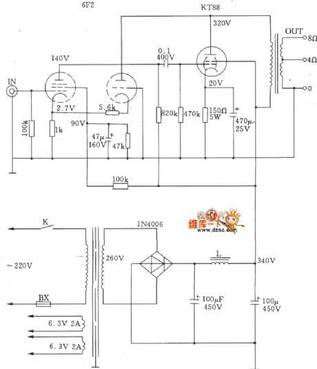
The singal terminal (A) power amplifier circuit of ultra 3-pole valve connection is shown as above.
(View)
View full Circuit Diagram | Comments | Reading(731)
TMS3450NL Digital Clock Integrated Circuit Diagram
Published:2011/7/3 1:35:00 Author:Vicky | Keyword: Digital Clock Integrated Circuit
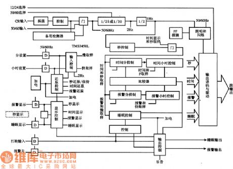
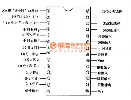
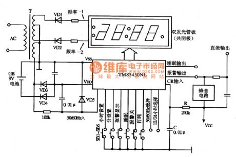
TMS3450NLis digital clock integrated circuit produced by Toshiba Corporation. It is widely used in various kinds of digital clock and auto clock circuit.
1 internal block circuit diagram and pin funtion
Internal block circuit diagram of TMS3450NL integrated circuit and the pin function are all shown in the above picture.
Internal block circuit diagram of IC TMS345ONL
Typical applied circuit of IC TMS345ONL
(View)
View full Circuit Diagram | Comments | Reading(19920)
| Pages:185/250 At 20181182183184185186187188189190191192193194195196197198199200Under 20 |
Circuit Categories
power supply circuit
Amplifier Circuit
Basic Circuit
LED and Light Circuit
Sensor Circuit
Signal Processing
Electrical Equipment Circuit
Control Circuit
Remote Control Circuit
A/D-D/A Converter Circuit
Audio Circuit
Measuring and Test Circuit
Communication Circuit
Computer-Related Circuit
555 Circuit
Automotive Circuit
Repairing Circuit