
Index 189
The common high-voltage multiplier circuit
Published:2011/6/28 0:49:00 Author:Borg | Keyword: high-voltage, multiplier
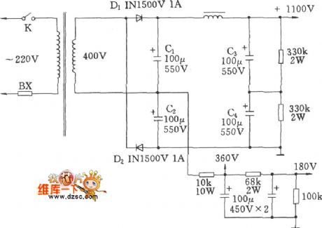
The common high-voltage multiplier circuit is shown as above.
(View)
View full Circuit Diagram | Comments | Reading(962)
The wireless microphone circuit of MC2831
Published:2011/6/28 0:39:00 Author:Borg | Keyword: wireless microphone
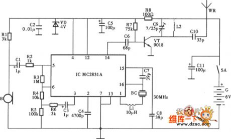
The wireless microphone circuit of MC2831 is shown as above.
(View)
View full Circuit Diagram | Comments | Reading(3467)
The 80v—12v/10A DC voltage converter circuit (2)
Published:2011/6/28 21:32:00 Author:qqtang | Keyword: voltage converter
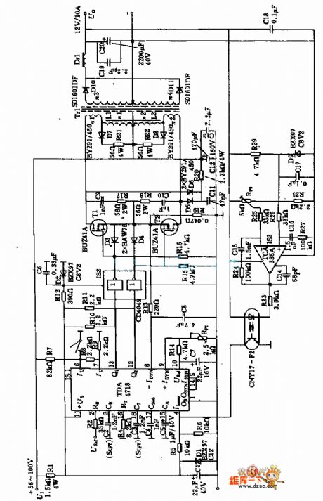
Figure:The 80v—12v/10A DC voltage converter circuit (2) (View)
View full Circuit Diagram | Comments | Reading(969)
The 80v—12v/10A DC voltage converter circuit (1)
Published:2011/6/28 21:38:00 Author:qqtang | Keyword: voltage converter, DC
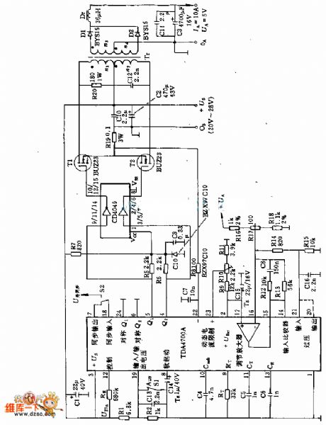
Figure: The 80v—12v/10A DC voltage converter circuit (1) (View)
View full Circuit Diagram | Comments | Reading(1565)
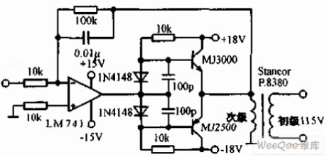
Server preamplifier circuit uses the parallel op-amp
Published:2011/6/19 19:50:00 Author:TaoXi | Keyword: Server, preamplifier, parallel op-amp
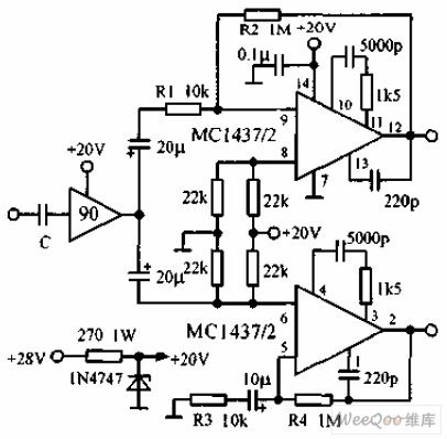
The server preamplifier circuit which uses the parallel op-amp is as shown in the figure, this circuit supplies the differential output to the 115V, 60Hz servo motor power amplifier. One op-amp is reversal-phase connected, another op-amp is in-phase connected to form the complementary output circuit. The voltage gain of this circuit is 40dB, and the single regulator tube supplies the power to this circuit. This circuit uses the depth DC negative feedback, so it has good DC stabilit. The bandwidth is 60KHZ, the input is drived by the 90°shifting phase.
(View)
View full Circuit Diagram | Comments | Reading(1553)
Cascaded MMIC amplifier circuit
Published:2011/6/20 0:05:00 Author:John | Keyword: amplifier
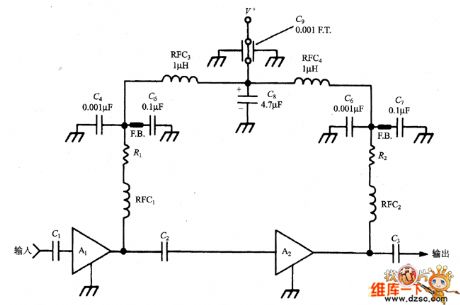
We must realize that MIC has different sizes of gain for the frequency range from DC to microwave region. For all cascaded amplifiers, we must prevent feedback between the different levels. Two factors must be noted here. Firstly, pay attention to the structure and layout as usual. External MIC input and output circuit must be physically isolated to prevent the coupling feedback. Secondly, DC power cord is needed for a decoupling of two or more stages. Signal on the DC power line are easy to be coupled between the different levels, causing unwanted feedback.
(View)
View full Circuit Diagram | Comments | Reading(1)
ISD4004 interface module circuit
Published:2011/6/19 3:14:00 Author:John | Keyword: interface module
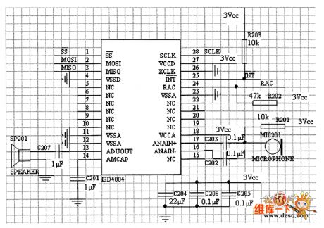
It can be seen from the figure that the circuit design is very simple. SPI port of ISD4004 SPI is directly connect with the microcontroller's SPI port. The ADUOUT of ISD4004 is directly connected to the audio output. A capacitor is placed on the audio output pin in order to achieve improvement of voice quality. ISD4004 audio output is connected with MICPHONE with the differential approach. ISD4004 interrupt output is pulled up through a resistor, then is connected with the microcontroller. The RAC pin of ISD4004 is for connecting with the general I / O port of MCU. As a result, the pin state can be controlled by the microcontroller.
(View)
View full Circuit Diagram | Comments | Reading(3798)
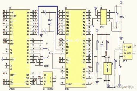
MODEM interface circuit
Published:2011/6/19 2:58:00 Author:John | Keyword: MODEM interface
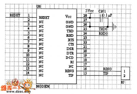
MODEM module has been understand well, so the design for its interface circuit is relatively easy. Although MODEM provides many control lines, considering the simplicity of the interface design and the connection between the MODEM module and a microcontroller through the UART, two lines (TXD, RXD) connection is needed. Communication control on MODEM is implementated through software. Using software control is rather flexible and is also a good way to avoid excessive hardware signal detection.
(View)
View full Circuit Diagram | Comments | Reading(570)
relay isolation circuit of DTL
Published:2011/6/15 7:16:00 Author:chopper | Keyword: relay, isolation circuit, DTL
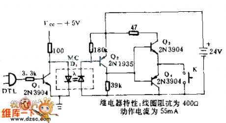
In this circuit,geminate transistors can counteract and prevent from generating natural current.When DTL logical cicuit outputs 1 ,Q1 will be conducted and LED is no current.Q2 will close,relay K1 will sotp running.When the DTL outputs 0 ,Q1 will close,and there is current through LED.Q2 will be conducted,K1 wil run.Action time is relative to mechanical response characteristic of relay.
(View)
View full Circuit Diagram | Comments | Reading(658)
Interface circuit between the serial 12-bit ADC and the computer
Published:2011/6/20 2:13:00 Author:TaoXi | Keyword: Interface circuit, serial 12-bit ADC, computer
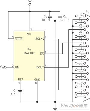
In recent years, the IC manufacturers design various methods to achieve the interface, and they pay special attention to reduce the I/O pin number of the IC interface. The MAX187 is such a device which is designed as the 12-bit D/A converter (ADC). You can use the serial data communication technology to produce a interface that matches the ADC. The A/D conversion and data transmission of the MAX187 only needs three digital I/O lines. You can use the PC's Centronics printer port to produce a simple interface between the MAX187 and PC (figure 1). As long as the pins are set to the high or low level, you can enable or disable the MAX187 (pin-3).
Figure 1 The interface between the 12-bit ADC and the PC (View)
View full Circuit Diagram | Comments | Reading(883)
CAN interface circuit
Published:2011/6/20 3:11:00 Author:TaoXi | Keyword: CAN, interface circuit
CAN interface circuit (View)
View full Circuit Diagram | Comments | Reading(837)
20W-60HZ servo circuit
Published:2011/6/20 4:16:00 Author:TaoXi | Keyword: 20W-60HZ, servo circuit
The 20W-60HZ servo circuit is as shown in the figure. This circuit adds two large current complementary transistors on the operational amplifier to make the servo amplifier to produce the 115V output voltage. The amplifier drives the low impedance 10V filament transformer, the primary stage and the subprime stage are reverse connected to improve the output voltage to 115V, the 115V output voltage can be used to drive the servo mechanism. The transistor needs to add the radiator.
(View)
View full Circuit Diagram | Comments | Reading(715)
28V servo power amplifier circuit
Published:2011/6/20 6:26:00 Author:TaoXi | Keyword: 28V, servo, power amplifier
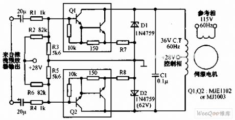
The 28V servo power amplifier circuit is as shown in the figure. This circuit uses the power Darlington tube to form the common-emitter configuration, and this circuit produces the high voltage and the current gain to drive the control phase position 60Hz servo mechanism. At the same time, in the case of without the transformer, this circuit supplies the high load impedance for the pre-amplifier circuit.
(View)
View full Circuit Diagram | Comments | Reading(781)
TA7376P dual track power amplification integrated circuit
Published:2011/6/16 1:07:00 Author:chopper | Keyword: dual track, power amplification, integrated circuit
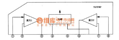
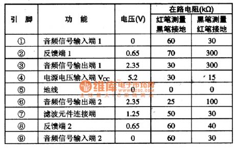
TA7376P is a dual track power amplification integrated circuit and it is of the characteristic that quiescent current is samll,power supply noise is low,output power is big,outward elements are few and so on.The scope of the working power supply is 4.5-9V,typical working voltage is 6V.1.The inner circuit and function of pins of TA7373FThe inner circuit of TA7373F integrated package is shown as picture 1.This IC adopts single inline 9 pinned package.Its function and data of pins are shown as chart 1.
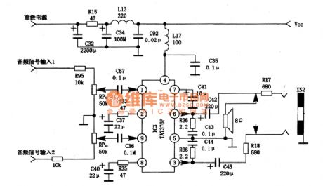
2.TA7376P typical application circuitThe typical application circuit of TA7376P integrated package is shown as picture 2.
(View)
View full Circuit Diagram | Comments | Reading(1121)
400Hz driving circuit
Published:2011/6/20 7:38:00 Author:TaoXi | Keyword: 400Hz, driving circuit
The 400Hz driving circuit can be used to improve the output power of the digital/synchronous transformation system, even if the circuit use the electrical resistance load, it also can get the stable, precise output gain, this circuit has the overcurrent protection function, it can continuously output the 400Hz, 95V RMS voltage to the 500Ω load, the power bandwidth is 50 kHz. When the load current is more than 300mA, the protection circuit will turn the current back to 200mA.
(View)
View full Circuit Diagram | Comments | Reading(857)
TA7232P dual audio power amplifition integrated circuit
Published:2011/6/14 3:32:00 Author:chopper | Keyword: dual audio power, amplifition, integrated circuit
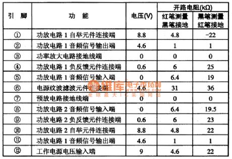
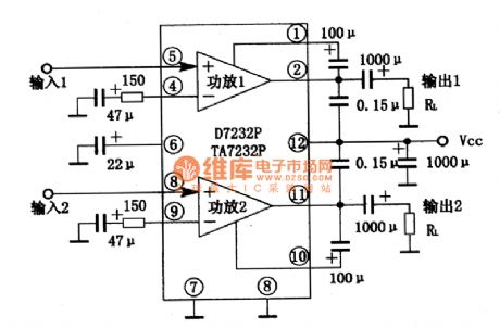
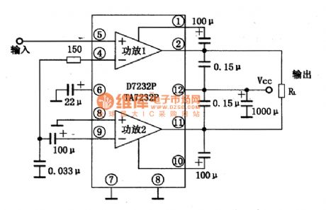
TA7232P is a dual track audio power amplifition integrated circuit produced by Company TOSHIBA,and it is applied to stereo radio and tape player,music center and so on as a power amplifier.1.The inner circuit and function of pins of TA7232PTA7232P integrated package inner circuit is formed by two audio power amplifition circuits of same function.Its integrated package inner circuit and typical application circuit which forms dual track are shown as picture 1.This IC adopts 12 pins single inline package,its function and data of pins of the integrated circuit are shown as chart 1.
(View)
View full Circuit Diagram | Comments | Reading(2805)
TA7215P dual track audio power amplifition integrated circuit
Published:2011/6/16 21:53:00 Author:chopper | Keyword: dual track, audio power, amplifition, integrated circuit
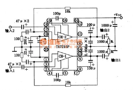
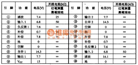
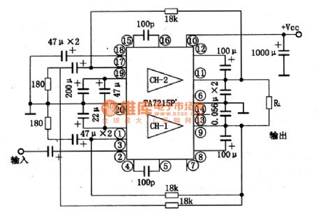
TA7215P is a dual track audio power amplifition integrated circuit,and it is applied to home-use audios and other tape recording players.1.inner circuit and typical application circuitThe inner circuit and typical application circuit of TA7215P integratedcircuit are shown as picture 1.This IC adopts dual inline 20 pinned package.Its function and data of pins of the integrated circuit are shown as chart 1.
2.the main electrical parameter of TA7215PThe scope of working power supply of TA7215P integrated circuit is 4.5-16V.When the load resistance RL=4Ω,THD=10%,f=1KHz,the output power of dual trackis 2.2W if Vcc=9V.
(View)
View full Circuit Diagram | Comments | Reading(2522)
STV9306 field scanning output integrated circuit
Published:2011/6/14 8:50:00 Author:chopper | Keyword: field scanning, output, integrated
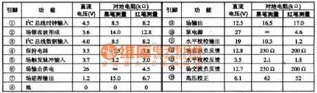
STV9306 integrated circuit is a field scanning output integrated circuit and it is applied to Changhong large-screen color TV widely.1.function characteristicsSTV9306 integrated circuit includes I2C bus interface circuit,field sawtooth wave shaping circuit,field output amplifition circuit,field blanking signal shaping circuit,horizontal pincushion processing circuit and so on.2.function and data of pinsThe function and data of pins of STV3906 integrated circuit are shown as chart 1.
(View)
View full Circuit Diagram | Comments | Reading(674)
44V AC driving circuit
Published:2011/6/20 6:33:00 Author:TaoXi | Keyword: 44V, AC, driving circuit
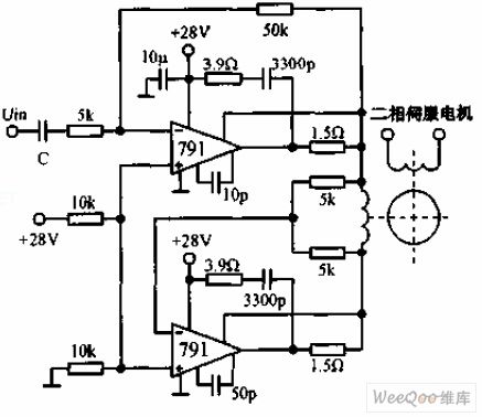
The 44V AC driving circuit uses two power operational amplifiers 791, the continuous power consumption rated value of every power operational amplifier is 10W, and the amplifiers are connected into the AC electric bridge. The upper 791's reversed phase gain is 10, the lower 791's reversed phase gain is on the AC servo motor.
(View)
View full Circuit Diagram | Comments | Reading(730)
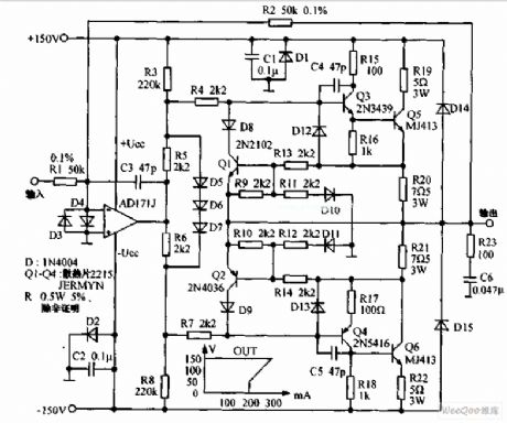
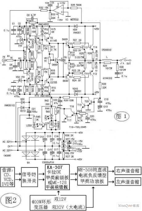
Meishun ME-308 pure DC current negative feedback class A power amplifier circuit
Published:2011/6/18 10:18:00 Author:Nancy | Keyword: pure DC current, negative feedback, power amplifier, class A
View full Circuit Diagram | Comments | Reading(1908)
| Pages:189/250 At 20181182183184185186187188189190191192193194195196197198199200Under 20 |
Circuit Categories
power supply circuit
Amplifier Circuit
Basic Circuit
LED and Light Circuit
Sensor Circuit
Signal Processing
Electrical Equipment Circuit
Control Circuit
Remote Control Circuit
A/D-D/A Converter Circuit
Audio Circuit
Measuring and Test Circuit
Communication Circuit
Computer-Related Circuit
555 Circuit
Automotive Circuit
Repairing Circuit