
Index 186
Semiconductor transistor basic amplifying circuit
Published:2011/7/3 20:58:00 Author:Christina | Keyword: Semiconductor, transistor, basic amplifying

When the amplifier circuit is amplifying the signal, it always has two electrodes to be used as the input port of the signal, and there are two electrodes to be used as the output port. There are three kinds of circuit according to the connection mode between the three electrodes of the semiconductor transistor and the input & output terminals: the common emitter circuit, the common base circuit and the common collector circuit. The connection modes of these circuits are as shown in figure.
Figure 1 The three connection modes of the semiconductor transistor basic amplifier circuit
(View)
View full Circuit Diagram | Comments | Reading(678)
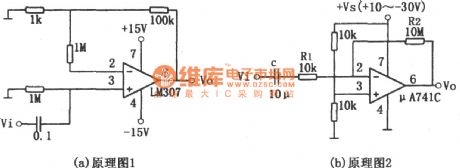
simple audio amplifition(LM307、μA741) circuit
Published:2011/7/1 0:08:00 Author:chopper | Keyword: simple, audio amplifition
(View)
View full Circuit Diagram | Comments | Reading(1006)
OPA2111 balanced stereo preamplifier circuit
Published:2011/7/1 0:26:00 Author:chopper | Keyword: balanced, stereo, preamplifier
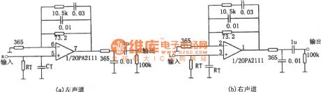
Figure shows a balanced stereo preamplifier circuit. Figure (a) is for the left channel preamplifier circuit,and Figure (b) is for the right channel preamplifier. The circuit uses a dual op-amp OPA2111. Left and right channels, respectively, use a op-amp of dual op-amp OPA2111.Thus the left and right channel have a good matching (gain differ is 3dB, bias differ is 0.5pA, drift differ is ± 0.5μV / ℃), and it is appropriate to constitutes a balanced stereo preamplifier. (View)
View full Circuit Diagram | Comments | Reading(1640)
low-noise preamplifier circuit of OPA37
Published:2011/7/1 0:53:00 Author:chopper | Keyword: low-noise, preamplifier circuit
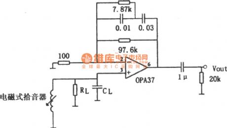
The picture shows the low-noise preamplifier of OPA37. The input signal is applied to OPA37 inverting input (pin 3). RL,CL in the circuit are the load impedances of the electromagnetic pick-up,and their resistances and capacities follow the characteristics of the pick-up(Generally they are based on the recommended parameters ). The all resistors should adopt metal film resistors (1% accuracy), and their capacitors should use organic film capacitors. When the input signal is 1kHz, its gain will be about 100 times. (View)
View full Circuit Diagram | Comments | Reading(1075)
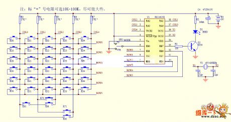
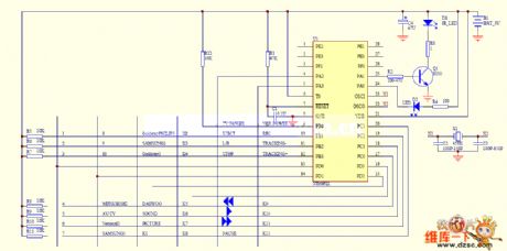
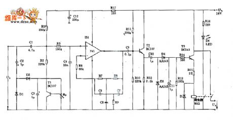
TV remote control 03 circuit
Published:2011/7/2 4:40:00 Author:John | Keyword: TV remote control
View full Circuit Diagram | Comments | Reading(884)
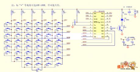
TV remote control 04 circuit
Published:2011/7/2 4:40:00 Author:John | Keyword: TV remote control
View full Circuit Diagram | Comments | Reading(659)
TV remote control 01 circuit
Published:2011/7/2 4:35:00 Author:John | Keyword: TV remote control
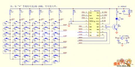
View full Circuit Diagram | Comments | Reading(655)
TV remote control 02 circuit
Published:2011/7/2 4:36:00 Author:John | Keyword: TV remote control
View full Circuit Diagram | Comments | Reading(738)
Push-twist circuit uses the complementary transistor and the CMOS driver stage
Published:2011/7/1 1:30:00 Author:TaoXi | Keyword: Push-twist circuit, complementary transistor, CMOS driver stage
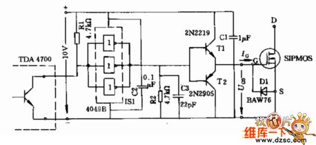
Figure: the Push-twist circuit uses the complementary transistor and the CMOS driver stage
(View)
View full Circuit Diagram | Comments | Reading(810)
Conversion amplifier circuit
Published:2011/7/1 0:54:00 Author:TaoXi | Keyword: Conversion, amplifier
The Conversion amplifier circuit is as shown in figure:
(View)
View full Circuit Diagram | Comments | Reading(624)
Programmable amplifier circuit with the high-speed gain
Published:2011/7/1 1:00:00 Author:TaoXi | Keyword: Programmable amplifier, high-speed gain
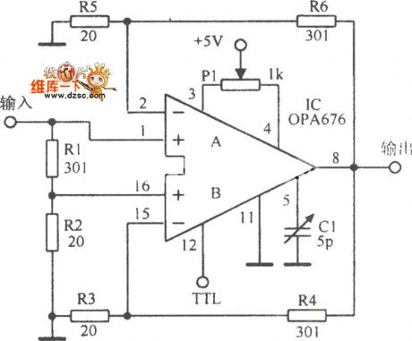
The Programmable amplifier circuit with the high-speed gain is as shown in the figure:
(View)
View full Circuit Diagram | Comments | Reading(715)
Practical adjustable ratio differential amplifier circuit
Published:2011/7/1 1:05:00 Author:TaoXi | Keyword: Practical, adjustable ratio, differential amplifier
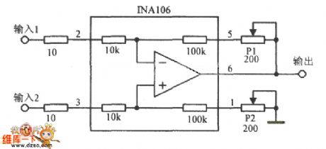
The Practical adjustable ratio differential amplifier circuit is as shown in the figure:
(View)
View full Circuit Diagram | Comments | Reading(715)
High performance logic command control gain amplifier circuit
Published:2011/7/1 1:08:00 Author:TaoXi | Keyword: High performance, logic command control, gain, amplifier
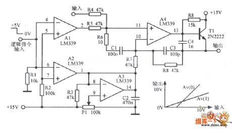
The High performance logic command control gain amplifier circuit is as shown in the figure:
(View)
View full Circuit Diagram | Comments | Reading(616)
PGA202/203 circuit based on the numerical control gain programming instrument amplifier
Published:2011/7/1 1:11:00 Author:TaoXi | Keyword: numerical control, gain, programming instrument, amplifier
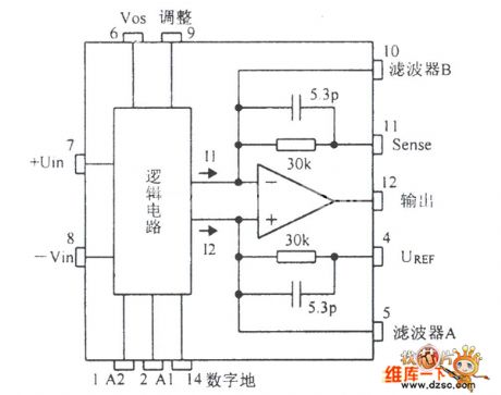
The PGA202/203 circuit based on the numerical control gain programming instrument amplifier is as shown in the figure:
(View)
View full Circuit Diagram | Comments | Reading(634)
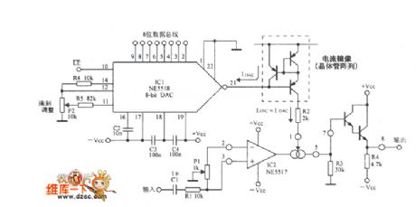
Low power consumption program-controlled gain amplifier circuit
Published:2011/7/1 1:14:00 Author:TaoXi | Keyword: Low power consumption, program-controlled, gain, amplifier circuit
The Low power consumption program-controlled gain amplifier circuit is as shown in the figure:
(View)
View full Circuit Diagram | Comments | Reading(880)
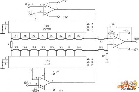
Digital programmable amplifier circuit
Published:2011/7/1 1:18:00 Author:TaoXi | Keyword: Digital, programmable amplifier
The Digital programmable amplifier circuit is as shown in the figure:
(View)
View full Circuit Diagram | Comments | Reading(592)
10W audio power amplification circuit of μPC1238
Published:2011/6/22 20:45:00 Author:chopper | Keyword: 10W, audio power, amplification
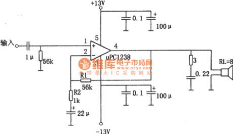
The picture shows a 10W audio power amplification circuit.This circuit adopts integrated power amplifier μPCI238 as the amplifying device.The input signal is added to the in-phase input end(pin 1) of operational amplifier through coupling capacitance(capacity is lμF) and resistor(resistance is 56kΩ).Between the output end (pin 4) and inverting input end(pin 2) is a feedback resistor R1 whose value is 56Ω,and between the inverting input end and groud are resistor R2 whose value is 1KΩ and a 22μF capacitor.The voltage amplification times of the circuit is:Av=(1+R1/R2)≈(1+56/1)=57 (View)
View full Circuit Diagram | Comments | Reading(1689)
audio firing key amplifition circuit formed by program-controlled op-amp F346
Published:2011/6/30 23:47:00 Author:chopper | Keyword: audio, firing key, amplifition, program-controlled, op-amp
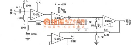
This is a audio firing key amplifition circuit formed by four program-controlled integrated operational amplifier F346.The constant-current source circuit of program-controlled operational amplifier can be controlled by external part,and when constant flow source is loaded to the current bias,the op-amp will be in functional mode,or it will be on cutoff state.Additionally, when the value of current bias is changed,the parameter of the op-amp will be changed,too. (View)
View full Circuit Diagram | Comments | Reading(725)
TA8149N recording,playback preamplification integrated circuit
Published:2011/6/30 2:48:00 Author:chopper | Keyword: recording, playback, preamplification, integrated circuit
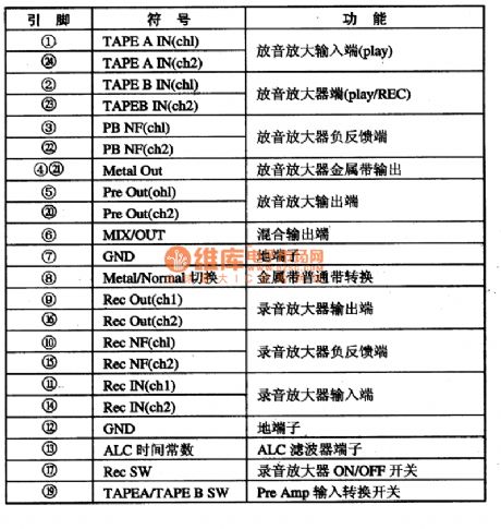
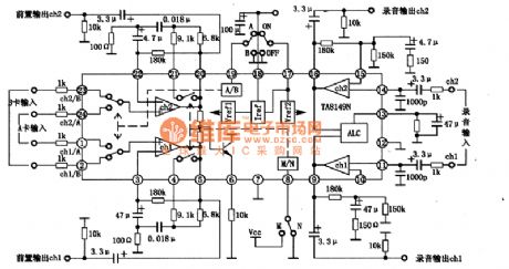
TA8149N is a recording,playback preamplification integrated circuit produced by Company TOSHIBA and used in double card machine,it is applied to the homemade and import music center widely.1.inner circuit and function of pins TA8149N integrated package includes two recording,playback preamplification circuits of same functions,metal tape/normal tape electronic switching convertion circuit,card A and card B electronic switching convertion circuit,ALC control circuit,power supply and bias voltage circuit.The inner circuit and typical application circuit are shown as picture 1.This IC adopts dual inline 24 pinned package,the functions of pins are shown as chart 1.
(View)
View full Circuit Diagram | Comments | Reading(1169)
preamplifier(OPA37) circuit of NAB magnetic head
Published:2011/6/30 2:33:00 Author:chopper | Keyword: preamplifier, NAB magnetic head
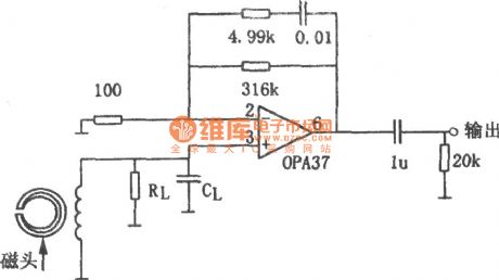
The picture is a preamplifier circuit of NAB magnetic head.This circuit adopts the magnetic head preamplifier formed by ultra-low noise and precise operational amplifier OPA37.This circuit can offer the standard NAB equal.When the frequency is 1kHz,the voltage amplifition time is 50db.The audio input signal is picked by magnetic head device and it is loaded to in-phase input end of OPA37.This connection method can make the operational amplifier possess high input impedance,that is to say,thepath between pin 3 of OPA37 and ground can be taken as a open circuit approximatively.The load impedance of magnetic head is formed by RL,CL and its resistance and capacity can be determined by the features of magnetic head device. (View)
View full Circuit Diagram | Comments | Reading(3123)
| Pages:186/250 At 20181182183184185186187188189190191192193194195196197198199200Under 20 |
Circuit Categories
power supply circuit
Amplifier Circuit
Basic Circuit
LED and Light Circuit
Sensor Circuit
Signal Processing
Electrical Equipment Circuit
Control Circuit
Remote Control Circuit
A/D-D/A Converter Circuit
Audio Circuit
Measuring and Test Circuit
Communication Circuit
Computer-Related Circuit
555 Circuit
Automotive Circuit
Repairing Circuit