
Index 184
The simple separation amplifier circuit of photoelectric coupler
Published:2011/7/4 20:12:00 Author:Borg | Keyword: separation amplifier, photoelectric coupler
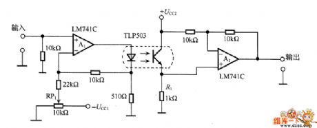
In the figure is the simple separation amplifier circuit of photoelectric coupler. This amplifier is used in the situation of low separation standard, the frequency width is 0~30kHz. In the circuit, RP1 is used to decide the bias, which makes the waveform distortion be the minimum. The DC bias and input signal are added together, which controls the forward current of the LED and makes A1 drive in with the constant current. The resistor R1 converts the current output by the photoelectric transistor into the voltage.
(View)
View full Circuit Diagram | Comments | Reading(733)
Transformer, RC circuit and direct-coupled amplifier circuit diagram
Published:2011/7/1 1:30:00 Author:Ecco | Keyword: Transformer, RC circuit , direct-coupled , amplifier
View full Circuit Diagram | Comments | Reading(986)
Classic 0-300MHz no Bote Wan band amplifier circuit diagram
Published:2011/7/1 2:19:00 Author:Ecco | Keyword: Classic , 0-300MHz , no Bote Wan band , amplifier

View full Circuit Diagram | Comments | Reading(761)
The oxygen concentrator circuit
Published:2011/6/13 21:57:00 Author:Seven | Keyword: oxygen inhaler
View full Circuit Diagram | Comments | Reading(4534)
The circuit of the oxygen inhaler
Published:2011/6/13 21:57:00 Author:Seven | Keyword: oxygen inhaler
View full Circuit Diagram | Comments | Reading(887)
The Changhong hp(5168) projection green primary video amplifier circuit
Published:2011/6/23 0:33:00 Author:qqtang | Keyword: projection, green primary, video amplifier circuit
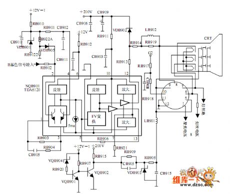
The Changhong hp(5168) projection green primary video amplifier circuit is shown in the figure.
(View)
View full Circuit Diagram | Comments | Reading(688)
The MOSFET A amplifier circuit
Published:2011/6/23 0:44:00 Author:qqtang | Keyword: MOSFET A, amplifier circuit
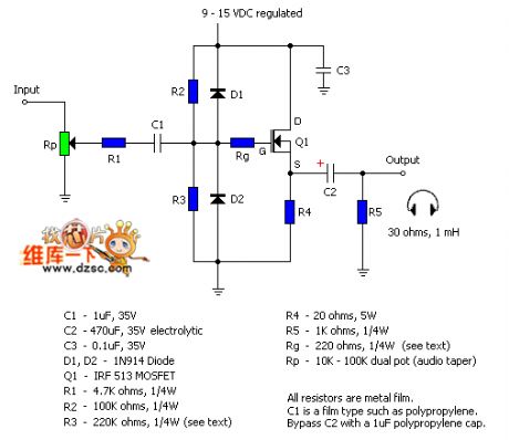
The MOSFET A amplifier circuit is shown in theabove figure.
C1-1uF, 35V R4-20 ohms, 5WC2-470uF, 35v electrolytic R5-1K ohms, 1/4WC3-0.1uF, 35v Rg-220 ohms, 1/4W (see text)D1,D2-1N914 Diode Rp-10K-100K dual pot(audio taper)Q1-IRF 513MOSFET R1-4.7K ohms,1/4WR2-100k ohms,1/4W R3-220K ohms,1/4W(see text)All resistors are metal film. C1 is a film type such as polypropylene. Bypass C2 with a 1uF polypropylene cape. (View)
View full Circuit Diagram | Comments | Reading(1042)
The typical application circuit of digital output angle sensor signal regulator UZZ9001
Published:2011/6/28 7:50:00 Author:qqtang | Keyword: typical application circuit, output angle
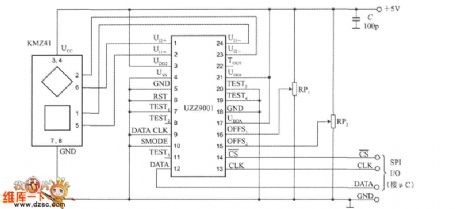
In the figure is the typical application circuit of UZZ9001. C represents the decoupling capacitor, SPI input/output connector can directly couple with single chip machine(μC), UZZ9001 can be set by the single chip machine. The error of the measuring angle of UZZ9001 is about ±0.35o.
(View)
View full Circuit Diagram | Comments | Reading(613)
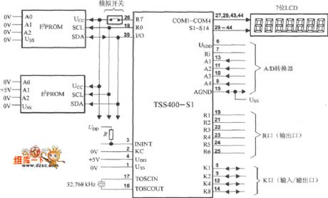
The typical application circuit of low-power programmable sensor signal processor TSS400-S1/S2
Published:2011/6/28 7:51:00 Author:qqtang | Keyword: application circuit, low-power, signal processor
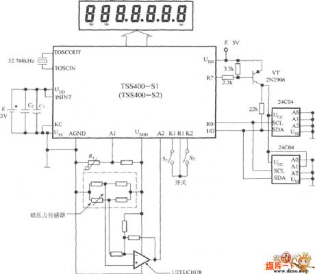
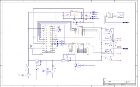
The typical application circuit of TSS400-S1/S2 is shown in the figure. This system is powered by the 3V LI battery(E), C1 and C2 is the decoupling capacitor of the power supply. The crystal frequency is 32.768KHz. The external storage is made of two pieces of 512 byte E2PROM of 24C04 type. In the dotted line frame is the silicon pressure sensor. With the temperature compensatory software, we can get the test precision and the 12-bit ADC pressure value. In the figure, all the analog wires are linked to USDD terminal, the sensor is powered only when it needs D/A conversion, by which the energy can be saved.
(View)
View full Circuit Diagram | Comments | Reading(702)
The general construction arrangement circuit of the low-power programmable sensor signal processor TSS400-S2
Published:2011/6/28 7:52:00 Author:qqtang | Keyword: general construction, low-power, programmable sensor
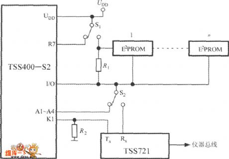
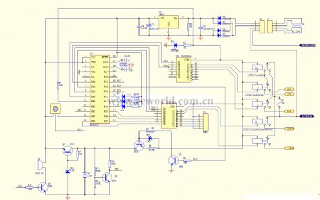
The general connection system allows a single way communication in a second line bus. This general line can be the twisted pair. Under the requirement of the host, the data are sent to the host from the affiliated machine. When the general line is effective, the affiliated host can also be started to send data asynchronously. The general connection of TSS400-S2 is shown in the figure. In the circuit, there is a chip general connector circuit TSS721. By the order of ENBUS, the distant reading of the additional module can be completed.
(View)
View full Circuit Diagram | Comments | Reading(749)
The typical system layout circuit of the low-power programmable sensor signal processor TSS400-S1
Published:2011/6/28 7:52:00 Author:qqtang | Keyword: typical system layout, low-power, signal processor
View full Circuit Diagram | Comments | Reading(639)
Complementary symmetry power amplifier circuit diagram
Published:2011/6/30 22:40:00 Author:Ecco | Keyword: Complementary , symmetry, power amplifier

View full Circuit Diagram | Comments | Reading(2030)
QS6K1 internal circuit
Published:2011/7/4 7:20:00 Author:John
View full Circuit Diagram | Comments | Reading(540)
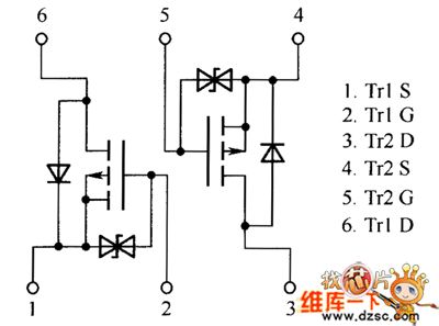
QS6J3 internal circuit
Published:2011/7/4 7:18:00 Author:John
View full Circuit Diagram | Comments | Reading(550)
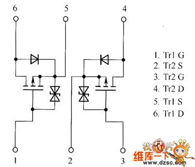
QS5U26 and QS5U28 internal circuit
Published:2011/7/4 7:07:00 Author:John
View full Circuit Diagram | Comments | Reading(582)
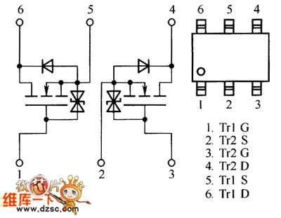
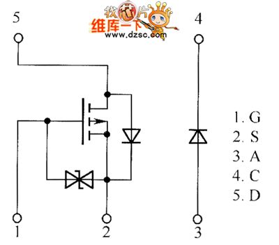
QS6J1 internal circuit
Published:2011/7/4 7:06:00 Author:John
View full Circuit Diagram | Comments | Reading(561)
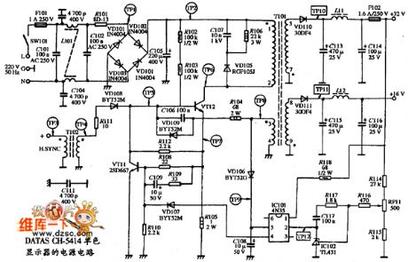
Monochrome display DATAS CH-5414 type power supply circuit
Published:2011/7/4 7:06:00 Author:John | Keyword: Monochrome display, power supply
View full Circuit Diagram | Comments | Reading(659)
The TDA2030A power amplifier circuit
Published:2011/6/25 5:28:00 Author:Borg | Keyword: power amplifier
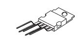
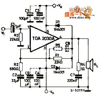
TDA2030A is the power amplifier circuit produced by Telefunken, which is V type 5-pin in-line plastic package.
Circuit features:1. Few external components; 2. Large output power, Po=18W(RL=4Ω); 3. it is in super small package(TO-220), which can raise the density; 4. little starting impact; 5. It contains all kinds of protection circuit, so it's safe and reliable. The main protection circuits are short protection, heat protection, earth wire occasional open circuit, power polarity inverted connection(Vsmax=12V) and loading releasing voltage reflection and so on.
(View)
View full Circuit Diagram | Comments | Reading(2170)
Increasing Input Impedance Circuit
Published:2011/6/21 19:41:00 Author:Robert | Keyword: Increasing, Input, Impedance
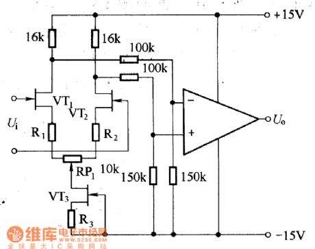
The picture shows the circuit which increases the input impedance by adding front amplifier stage.
Those amplifier circuit, which used in small current amplification or large signal internal resistance case, needs very high input impedance. Some could be more than 1x10¹²Ω. To increase the input impedance, the most direct way is to use the input stage composed of FET and add it in parallel before the amplifier. The circuit in the picture can make the VT2 static working point stable. R1, R2 and RP1 is used to get the balance of the output voltage of the front amplifier stage. (View)
View full Circuit Diagram | Comments | Reading(704)
VHF VFO circuit
Published:2011/7/4 6:56:00 Author:John | Keyword: VHF, VFO
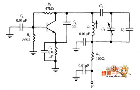
The author has encountered a device which has both drifting and shifting problems. These two kinds of problems both have a high ratio. Although employed in the communications sector at that time, I had not solved the problems for months ( cobbler's shoes syndrome). A closer examination was given to only find that there is some debris below the rotor of main tuning capacitor. Under normal circumstances, the rotor of the capacitance is connected to the chassis through its frame. But a brass or iron triangle of ground or spring clip should be placed around the bearing in front of the rotor because the rotor must rotate.
(View)
View full Circuit Diagram | Comments | Reading(1743)
| Pages:184/250 At 20181182183184185186187188189190191192193194195196197198199200Under 20 |
Circuit Categories
power supply circuit
Amplifier Circuit
Basic Circuit
LED and Light Circuit
Sensor Circuit
Signal Processing
Electrical Equipment Circuit
Control Circuit
Remote Control Circuit
A/D-D/A Converter Circuit
Audio Circuit
Measuring and Test Circuit
Communication Circuit
Computer-Related Circuit
555 Circuit
Automotive Circuit
Repairing Circuit