
Index 188
LM386 universal audio power amplifier circuit
Published:2011/6/29 0:38:00 Author:chopper | Keyword: universal, audio power amplifier
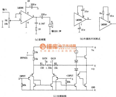
The picture is a universal audio power amplifier circuit.The picture (a) shows the principle,and this circuit adopts integrated power amplifier LM386.This element is a universal power amplifier and it is cheap.The picture (c) shows the inner structure of LM386.
(View)
View full Circuit Diagram | Comments | Reading(1845)
2W audio power amplifier circuit of LM380
Published:2011/6/29 0:55:00 Author:chopper | Keyword: 2W, audio power amplifier
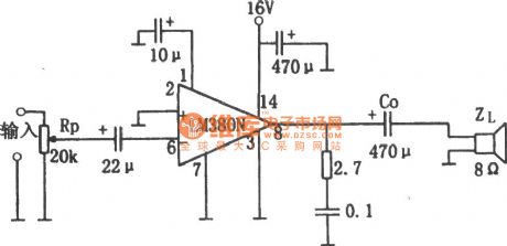
The picture is a 2W audio power amplifier circuit.This circuit adopts 14 pinned LM380 as the amplifier.Add the input signal to the inverting input end(pin 6) of operational amplifier LM380 through the volume control potentiometer Rp(20kΩ) and 22μF coupling capacitor and its in - phase input end (pin 2) is used to earth,pin 1 is circumscribed with 10μF filter capacitor to eliminate the high frequency ripple interference.The circuit adopts 16V single power supply,and circumscribes a 470μF decoupling capacitor between supply end(pin 14) and ground.Between the output end(pin 8) and ground there are two parallel branches.
(View)
View full Circuit Diagram | Comments | Reading(2901)
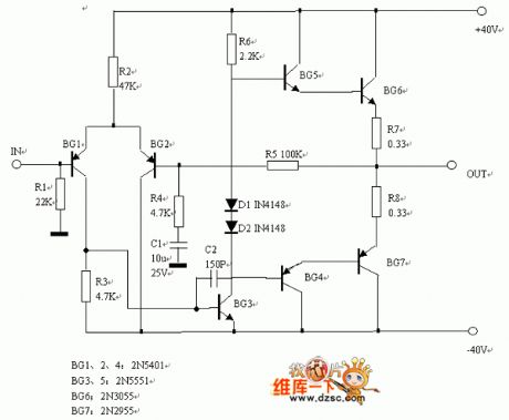
The 811 transistor power amplifier circuit
Published:2011/6/29 4:53:00 Author:Seven | Keyword: transistor, power amplifier
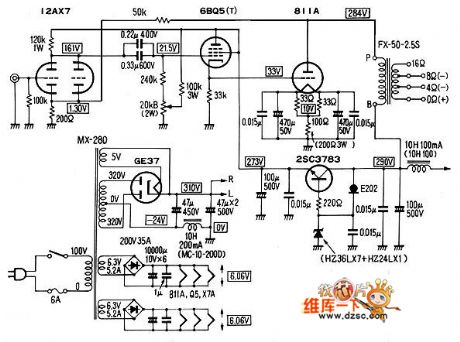
The 811 transistor power amplifier circuit is shown as above.
(View)
View full Circuit Diagram | Comments | Reading(2879)
The 811A push-pull 30W power amplifier circuit
Published:2011/6/29 5:25:00 Author:Seven | Keyword: push-pull, power amplifier
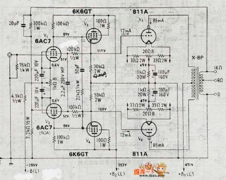
The 811A push-pull 30W power amplifier circuitis shown as above.
(View)
View full Circuit Diagram | Comments | Reading(6902)
The supreme TA-292C gallstone mixing rear stage power supply circuit
Published:2011/6/29 5:42:00 Author:Seven | Keyword: gallstone, rear stage, power supply
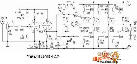
The supreme TA-292C gallstone mixing rear stage power supply circuit is shown above.
The gallstone mixing power amplifier of beautiful sound (View)
View full Circuit Diagram | Comments | Reading(1488)
The 100W power supply circuit
Published:2011/6/29 5:44:00 Author:Seven | Keyword: power supply
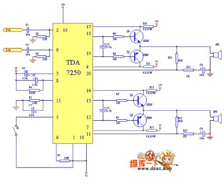
The 100W power supply circuit driven by TDA7250 is shown as above.
(View)
View full Circuit Diagram | Comments | Reading(1611)
The IM3886 woofer power amplifier circuit
Published:2011/6/29 5:02:00 Author:Seven | Keyword: woofer, power amplifier
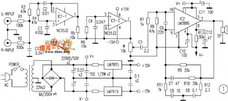
The IM3886 woofer power amplifier circuit is shown as above.
(View)
View full Circuit Diagram | Comments | Reading(1442)
The OCL and OTL power supply circuit
Published:2011/6/29 4:59:00 Author:Seven | Keyword: OCL, OTL, power supply
The OCL and OTL power supply circuit is shown as above.
(View)
View full Circuit Diagram | Comments | Reading(3567)
The push-pull circuit of 6P1
Published:2011/6/29 6:14:00 Author:Seven | Keyword: push-pull
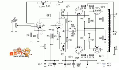
The push-pull circuit of 6P1 is shown as follows.
(View)
View full Circuit Diagram | Comments | Reading(3580)
The KSA100 wiring circuit of Krell classical power amplifier
Published:2011/6/29 6:22:00 Author:Seven | Keyword: wiring circuit, Krell, power amplifier
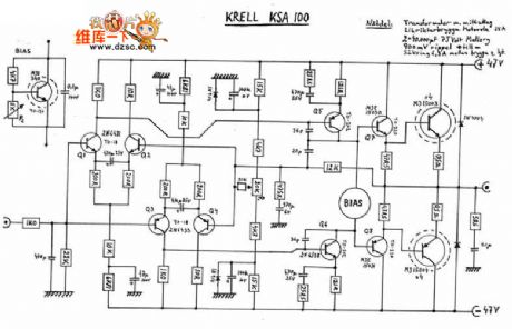
The KSA100 wiring circuit of Krell classical power amplifier is shown as above.
(View)
View full Circuit Diagram | Comments | Reading(5523)
The DSP connector circuit
Published:2011/6/29 7:34:00 Author:Seven | Keyword: DSP connector
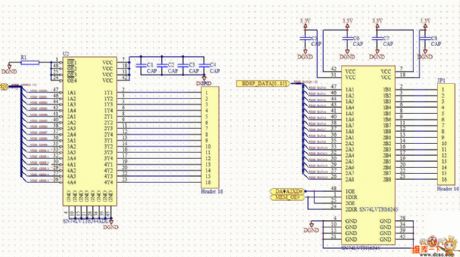
The DSP connector circuit is shown in the figure.
(View)
View full Circuit Diagram | Comments | Reading(917)
Typical Applied Diagram of Integrated Circuit
Published:2011/6/26 9:15:00 Author:Vicky | Keyword: Typical Applied Diagram, Integrated Circuit
Picture: Typical Applied Circuit of LM331 Integrated Circuit (View)
View full Circuit Diagram | Comments | Reading(517)
The DC servo separator amplifier circuit of photoelectric coupler
Published:2011/6/28 0:59:00 Author:Borg | Keyword: DC servo, amplifier, photoelectric coupler
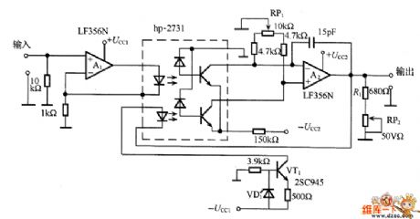
In the figure is the DC servo separator amplifier of photoelectric coupler. This circuit is transmitting DC signals in the servo way, which has a feedback loop, so the high stabilization is got. VT1 and so on compose a constant circuit, which drives the LED in the photoelectric coupler hp-2731, and offers the bias current of 4mA when the signal is 0. Hp-2731 is the double photoelectric coupler, which has the tracking function, to make the circuit stable, what needs to be make sure is that the current in each LED is equal. A2 is the differential amplifier.
(View)
View full Circuit Diagram | Comments | Reading(1184)
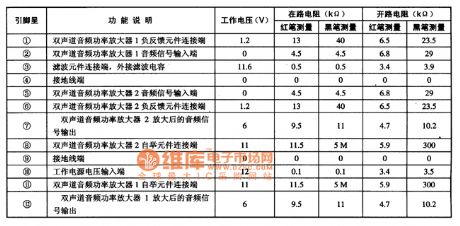
AN7178 dual-channel power amplifier integrated circuit
Published:2011/6/28 7:47:00 Author:Christina | Keyword: dual-channel, power amplifier, integrated circuit
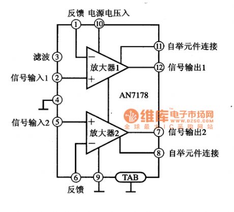
The AN7178 is designed as one kind of dual-channel power amplifier integrated circuit that is produced by the Panasonic company, it can be used in the Home audio equipments and the car audio equipments.
1.Features
The AN7178 has two channels of audio power amplifier circuit with the same function, and it has the over-voltage protection and overheating protection circuit. The features of this device are less external components, small distortion and the heat sink is easy to install. The internal circuit block diagram of the AN7178 is as shown in figure 1.
Figure 1. The internal circuit block diagram of the AN7178
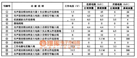
2.Pin functions and data
The AN7178 uses the 12-pin single row package, the pin functions and data is as shown in table 1.
Table 1 The pin functions and data of the AN7178
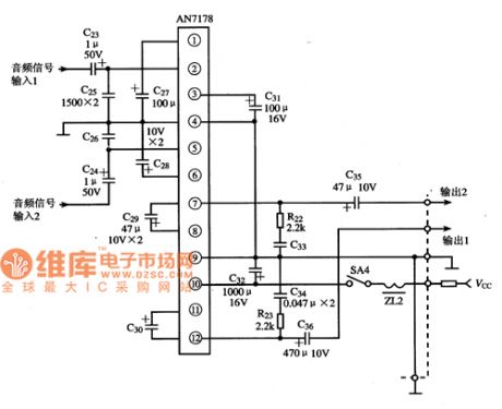
3. The typical application circuit
Figure 2. The typical application circuit of the AN7178
(View)
View full Circuit Diagram | Comments | Reading(3321)
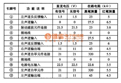
AN7168 duan-channel power amplifier integrated circuit
Published:2011/6/28 7:56:00 Author:Christina | Keyword: duan-channel, power amplifier, integrated circuit
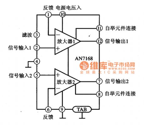
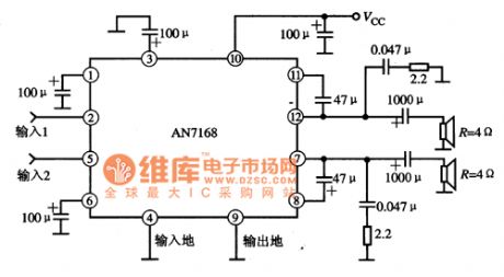
The AN7168 is designed as one kind of dual-channel power amplifier integrated circuit that is produced by the Panasonic company, it can be used in the Home audio equipments and the car audio equipments.
1.Features
The AN7168 has the over-voltage protection circuit, the over-current protection circuit, the over-temperature protection circuit and two channels of audio amplifier circuits, it has the features of low distortion, small power supply switching noise and less external components. The internal circuit block diagram is as shown in figure 1.
Figure 1 The internal circuit block diagram of the AN7168
2.Pin functions and data
The AN7168 uses the 12-pin single row package, the pin functions and data is as shown in table 1.
Table 1 The pin functions and data of the AN7168
3. The typical application circuit
Figure 2 The typical application circuit of the AN7168
(View)
View full Circuit Diagram | Comments | Reading(1904)
AN7147N duan-channel power amplifier integrated circuit
Published:2011/6/28 8:04:00 Author:Christina | Keyword: duan-channel, power amplifier, integrated circuit
The AN7147N is designed as one kind of duan-channel power amplifier integrated circuit that is produced by the Panasonic company, and it can be used in the large screen color TVs which uses the Panasonic movements.
1.Features
The AN7147N is composed of two channels of audio power amplifier circuit with the same function, the overheating and short circuit protection circuit and other auxiliary function circuits. The output power of every sound channel is about 12.5W.
2.Pin functions and data
The AN7147N uses the 12-pin single row DIP package, the pin functions and data are as shown in table 1.
Table 1 The pin functions and data of the AN7147N
(View)
View full Circuit Diagram | Comments | Reading(1625)
AN7124 duan-channel power amplifier integrated circuit
Published:2011/6/29 1:02:00 Author:Christina | Keyword: duan-channel, power amplifier, integrated circuit
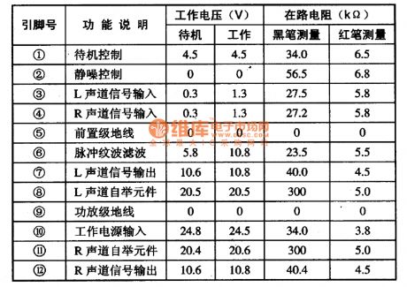
The AN7124 duan-channel power amplifier integrated circuit is produced by the Panasonic company that can be used in the large screen color TVs that use the Panasonic series machine.
1.Features
The AN7124 is composed of the two channels of power amplifier circuits with the same function, the standby control circuit, the static noise control circuit and the over-temperature and short circuit protection circuit.etc. The output power of the single track is about 15W.
2.Pin functions and data
The AN7124 uses the 12-pin single dual DIP package, the pin functions and data are as shown in table 1.
Table 1 The pin functions and data of the AN7124
(View)
View full Circuit Diagram | Comments | Reading(846)
The thermoregulation heater circuit
Published:2011/6/28 20:55:00 Author:qqtang | Keyword: thermoregulation heater
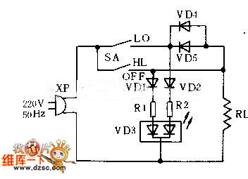
The thermoregulation heater circuit is shown in the figure. It is divided into off , Lo AND HL 3 gears. When the converting switch is pulled from SA to Lo, the 220V mains is added on the two terminals of loading RL by VD4 and VD56; due to the half-wave rectification of the diode, the working voltage of RL is obviously lower than that when the 220v current is passable directly, so the temperature of RL is falling down.
(View)
View full Circuit Diagram | Comments | Reading(770)
The OTL power amplifier power supply current circuit
Published:2011/6/28 0:38:00 Author:Borg | Keyword: OTL, power amplifier, power supply
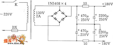
The OTL power amplifier power supply current circuit is shown as above.
(View)
View full Circuit Diagram | Comments | Reading(1104)
The stereo OTL power amplifier circuit of 6N5P valve
Published:2011/6/28 0:48:00 Author:Borg | Keyword: stereo, power amplifier, valve
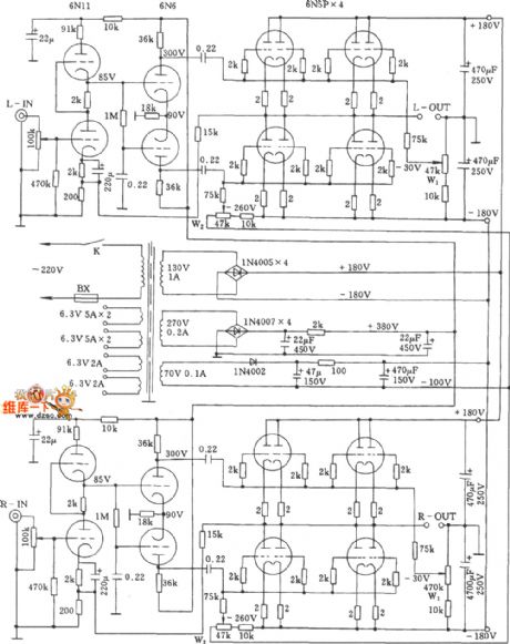
The stereo OTL power amplifier circuit of 6N5P valve is shown as above.
(View)
View full Circuit Diagram | Comments | Reading(2599)
| Pages:188/250 At 20181182183184185186187188189190191192193194195196197198199200Under 20 |
Circuit Categories
power supply circuit
Amplifier Circuit
Basic Circuit
LED and Light Circuit
Sensor Circuit
Signal Processing
Electrical Equipment Circuit
Control Circuit
Remote Control Circuit
A/D-D/A Converter Circuit
Audio Circuit
Measuring and Test Circuit
Communication Circuit
Computer-Related Circuit
555 Circuit
Automotive Circuit
Repairing Circuit