
Index 159
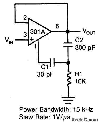
×10_OPERATIONAL_AMOLIFIER_USING_L161
Published:2009/6/23 3:00:00 Author:May
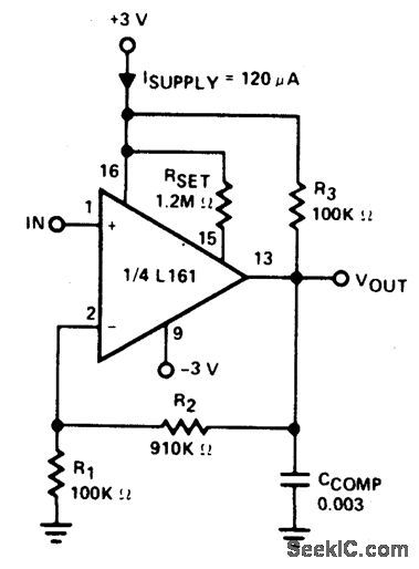
Amplifier is 3 dB down at 100 kHz and has a slew rate of 0.02V/μ sec. (View)
View full Circuit Diagram | Comments | Reading(545)
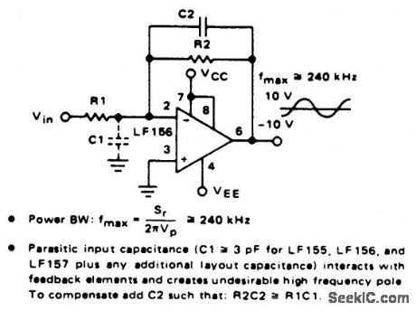
×100_OPERATIONAL_AMLIFIER_USING_L161
Published:2009/6/23 2:59:00 Author:May
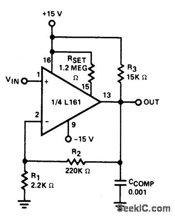
Amplifier has gain-bandwidth priduct of 20 MHz with slew rate of 0.3V/μ sec. (View)
View full Circuit Diagram | Comments | Reading(612)
SUMMING_AMPLIFIER_WITH_LOW_INPUT_CURRENT
Published:2009/6/23 2:57:00 Author:May
View full Circuit Diagram | Comments | Reading(703)
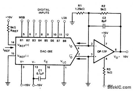
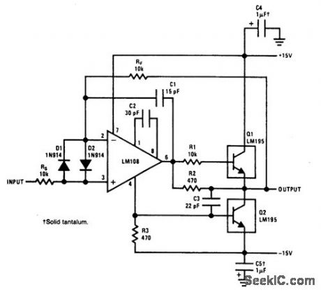
HIGH_SPEED_CURRENT_TO_VOLTAGE_OUTPUT_AMPLIFIER
Published:2009/6/23 2:48:00 Author:May
View full Circuit Diagram | Comments | Reading(591)
DIFFERENTIAL_AMPLIFIER_FOR_SCOPES
Published:2009/6/23 2:47:00 Author:May
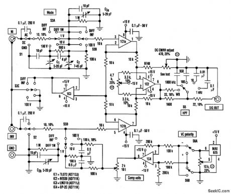
Differential inputs and comparator modes can be added to any general-purpose oscilloscope using this circuit setup. Calibration doesn't change because the circuit operates in unity gain in most modes. Amplifier noise level is low enough not to degrade low-level signals, and its dynamic range can handle signals up to ±12V peak. Notice that all of the resistors are 1%, unless specified otherwise. (View)
View full Circuit Diagram | Comments | Reading(3266)
FAST_VOLTAGE_FOLLOWER
Published:2009/6/23 2:44:00 Author:May
View full Circuit Diagram | Comments | Reading(687)
ISOLATION_AMPLIFIER_FOR_CAPACITIVE_LOADS
Published:2009/6/23 2:43:00 Author:May
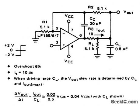
View full Circuit Diagram | Comments | Reading(620)
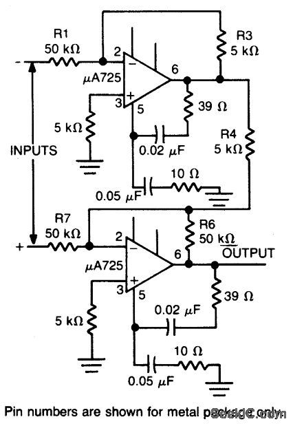
WIDE_BANDWIDTH_LOW_NOISE_LOW_DRIFT_AMPLIDIER
Published:2009/6/23 3:06:00 Author:Jessie
View full Circuit Diagram | Comments | Reading(630)
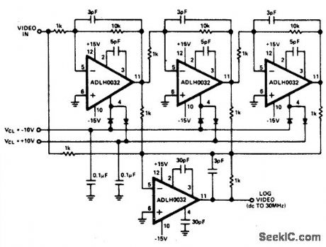
DC_TO_VIDEO_LOG_AMPLIFIER
Published:2009/6/23 3:05:00 Author:Jessie
View full Circuit Diagram | Comments | Reading(564)
±100_V_COMMON_MODE_RANGE_DIFFERENTIAL_AMPLIFIER
Published:2009/6/23 3:04:00 Author:Jessie
View full Circuit Diagram | Comments | Reading(491)
ULTRA_LOW_LEAKAGE_PREAMP
Published:2009/6/23 3:03:00 Author:Jessie

Input leakage-2 pA at 75℃. (View)
View full Circuit Diagram | Comments | Reading(585)
AMPLIFIER_COOL_DOWN_CIRCUIT_II
Published:2009/6/23 2:37:00 Author:May
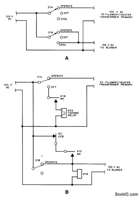
High-power amplifiers used In RE service,usmg vacuum tubes,often benefit from leaving the blower air flow on after removal of filament/heater voltage. (View)
View full Circuit Diagram | Comments | Reading(617)
SIMPLE_SCHMITT_TRIGGER
Published:2009/6/23 2:34:00 Author:May
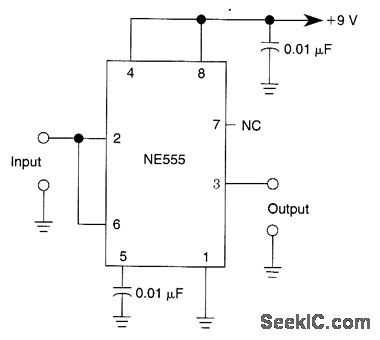
A 555 IC is shown configured to function as a Schmitt trigger. Inputs above and below the threshold level will turn the circuit on and off producing a square wave output. (View)
View full Circuit Diagram | Comments | Reading(941)
ADJUSTMENT_FREE_PRECISION_SUMMING_AMPLIFIER
Published:2009/6/23 2:55:00 Author:Jessie
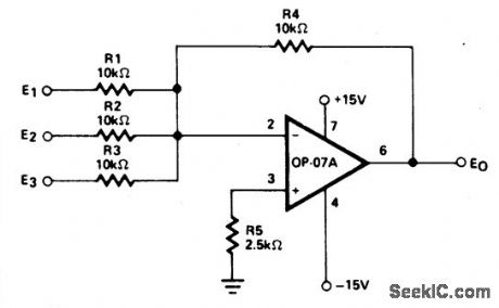
This circuit priduces continuous outputs that are a function of multiple input variables. (View)
View full Circuit Diagram | Comments | Reading(730)
1_A_VOLTAGE_FOLLOWER
Published:2009/6/23 2:53:00 Author:Jessie
This power voltage follower is good to 300 kHz. (View)
View full Circuit Diagram | Comments | Reading(578)
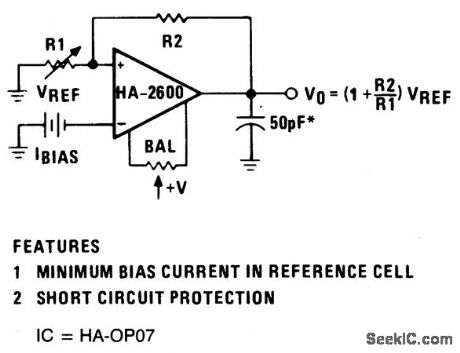
REFERENCE_VOLTAGE_AMPLIFIER
Published:2009/6/23 2:53:00 Author:Jessie
View full Circuit Diagram | Comments | Reading(627)
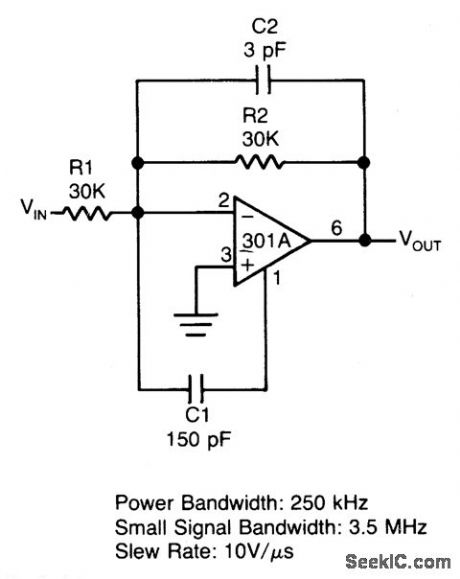
FAST_SUMMING_AMPLIFIER
Published:2009/6/23 2:52:00 Author:Jessie
View full Circuit Diagram | Comments | Reading(584)
GATED_AMPLIFIER
Published:2009/6/23 2:52:00 Author:Jessie
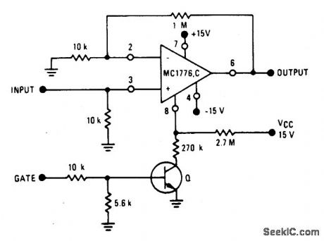
View full Circuit Diagram | Comments | Reading(732)
COLOR_VIDEO_AMPLIFIER
Published:2009/6/23 2:17:00 Author:May
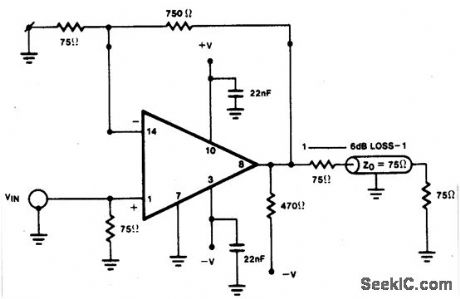
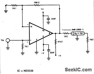
View full Circuit Diagram | Comments | Reading(894)
NONINVERTING_VOLTAGE_FOLLOWER
Published:2009/6/23 2:16:00 Author:May

View full Circuit Diagram | Comments | Reading(598)
| Pages:159/250 At 20141142143144145146147148149150151152153154155156157158159160Under 20 |
Circuit Categories
power supply circuit
Amplifier Circuit
Basic Circuit
LED and Light Circuit
Sensor Circuit
Signal Processing
Electrical Equipment Circuit
Control Circuit
Remote Control Circuit
A/D-D/A Converter Circuit
Audio Circuit
Measuring and Test Circuit
Communication Circuit
Computer-Related Circuit
555 Circuit
Automotive Circuit
Repairing Circuit