
Microphone
Index
The Big-E Stereo Parabolic Microphone
Published:2013/3/10 22:58:00 Author:Ecco | Keyword: Big-E , Stereo, Parabolic Microphone
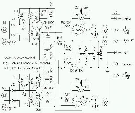
The circuit consists of two identical audio channels and some basic power supply filtering components. Only the left channel will be described.
The mini condenser microphone converts sounds into an electrical signal. Resistor R1 provides bias for the condensor microphone's internal amplifier transistor. The 2N3906 PNP transistor acts as a low noise microphone input amplifier. The 10K gain potentiometer is used for adjusting the audio signal level. A stereo 10K audio taper pot can be used for adjusting both channels simultaneously, or individual 10K trimmers can be used for fixed gain applications. The preamp output signal is fed into the 1458 op-amp, which boosts the audio to a level that is sufficient for driving an 8-ohm headphone or a tape recorder input. The 1458 amplifier stage is fixed gain (10X) in the inverting configuration, it drives the headphone speakers.
Capacitor C9 provides DC isolation from the 1458 op-amp output, which sits at half of the supply voltage. Resistor R13 provides impedance protection for the op-amp output and reduces audio distortion when driving low impedance headphones.
DC bias for the 1458 op-amps is set at half of the supply voltage by the R16/R17 voltage divider. Capacitors C13 and C14 filter the DC power supply for the op-amp stage. The DC is further filtered for the input preamp transistors through resistor R15 and capacitor C11. Diode D1 and resistor R18 protect the circuit from reverse battery polarity.
(View)
View full Circuit Diagram | Comments | Reading(1762)
4 microphones mixer circuit with TL081
Published:2012/9/11 20:29:00 Author:Ecco | Keyword: 4 microphones , mixer
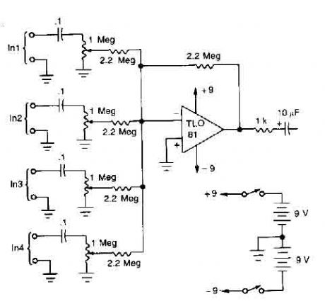
A TL081 op amp is used as a high impedance to low. converter and a signal mixer. The input impedance is about 1 megohm and the output impedance is about 1 kohm. Two 9 volt batteries are used as power source. (View)
View full Circuit Diagram | Comments | Reading(0)
Simple long-distance wireless microphone circuit
Published:2012/8/27 21:45:00 Author:Ecco | Keyword: Simple, long-distance, wireless microphone
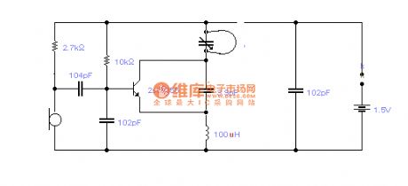
The loop antenna L1 for emission also serves as the oscillation coil, the high frequency current flowing in antenna has the same resonance with the oscillation frequency, so it is always in the best emission state. In practice, the launching distance is about 100-1850M in empty area ( receivers is a the Pocket Radio TOLY1781, and the receiver distance of antenna is added as 0.8m ), in contrast, under the equivalent working voltage, current and emission frequency, if L1 is changed by an ordinary spiral circle, oscillation transistor collector is connected to a 5PF capacitor with a 0 . 8M trolley line, the two launching transmission distances are almost equivalent to prove that the concealed shaped antenna, which is also used as the oscillator coil, has a quite high emission efficiency.
(View)
View full Circuit Diagram | Comments | Reading(3592)
FM wireless microphone circuit with voltage regulator circuit
Published:2012/8/21 1:53:00 Author:Ecco | Keyword: FM , wireless microphone , voltage regulator
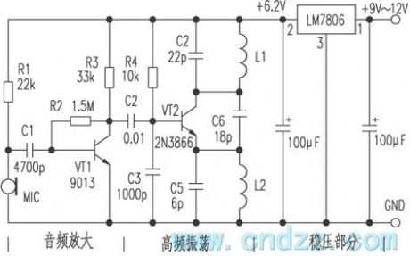
The circuit consists of three parts: 1 . Audio amplifier section; 2 . High-frequency oscillation part; 3 . Regulators parts. The signal is sent into a base of the transistor VT1 from the microphone MIC, then it is coupled to the base of high-frequency oscillation circuit VT2 by C2 after being amplified by VT1, then it is emitted by antenna. The working frequency of this circuit is between 85 ~ 104MHz. MIC selects high-sensitivity electret microphone, VT1 uses 9013H with β ≥ 125. VT2 is 2N3866 with β ≥ 90, L1, L2 use∮ 0.71mm enameled wires with four turns and 10 turns around ordinary pen core, C4, C5, C6 use ceramic capacitors, error is ± 5 % . The three-terminal regulator uses the LM7806 power supply with 9V battery, and the circuit board can be made by yourself.
(View)
View full Circuit Diagram | Comments | Reading(3024)
WIRELESS_AM_MICROPHONE
Published:2009/6/30 2:59:00 Author:May
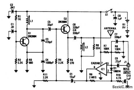
Transistor Q1 and its associated components comprise a tuneable rf oscillator. The rf signal is fed to transistor Q2, the modulator. Operational amplifier IC1 increases the audio signal and applids it through resistor R4 to the base of Q2. Tune an AM radio to an unused frequency between 800 to 1600 kHz. Tune L1 for a change in the audio level coming from the radio. Peak the output by adjusting L2. If L1 is disturbed, it may be necessary to readjust L2 for peak performance. Depending on the impedance of the microphone audio sensitivity can be increased by decreasing the value of R10 and vice versa. (View)
View full Circuit Diagram | Comments | Reading(1304)
UNDERWATER_MICROPHONE
Published:2009/6/23 2:17:00 Author:May
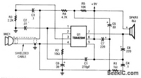
This circuit uses a TBA820 audio IC to amplify underwater sounds. The microphone must be waterproofed. This project was originally used in a home aquarium to monitor fish sounds. (View)
View full Circuit Diagram | Comments | Reading(2564)
SIMPLE_EXTERNAL_MICROPHONE_CIRCUIT_FOR_TRANSCEIVERS
Published:2009/6/23 2:11:00 Author:May
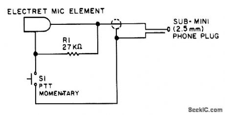
Used originally for an Icom ICZAT handie talkie, this circuit might prove useful in other applications. (View)
View full Circuit Diagram | Comments | Reading(963)
Dual-band wireless microphone receiver circuit
Published:2011/3/31 4:03:00 Author:Joan | Keyword: Dual-band , wireless , microphone receiver
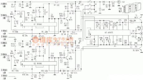
Above is Dual-band wireless microphone receiver circuit. (View)
View full Circuit Diagram | Comments | Reading(4999)
Wireless microphone circuit
Published:2011/3/21 2:52:00 Author:Joan | Keyword: Wireless microphone
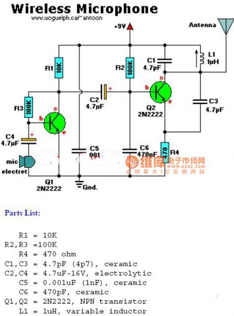
The figure is Wireless microphone circuit.
(View)
View full Circuit Diagram | Comments | Reading(3204)
Circuit Categories
power supply circuit
Amplifier Circuit
Basic Circuit
LED and Light Circuit
Sensor Circuit
Signal Processing
Electrical Equipment Circuit
Control Circuit
Remote Control Circuit
A/D-D/A Converter Circuit
Audio Circuit
Measuring and Test Circuit
Communication Circuit
Computer-Related Circuit
555 Circuit
Automotive Circuit
Repairing Circuit