About SeekIC | Services | Payment | Advertisements service | Contact Us | Links
© 2008-2012 SeekIC.com Corp.All Rights Reserved.
Published:2011/4/14 6:50:00 Author:may | Keyword: Voltage changer, blocking oscillator | From:SeekIC
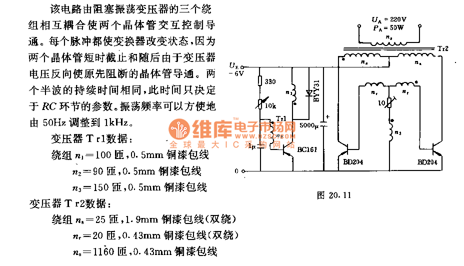
This circuit is mutual coupling by three windings of blocking oscillator transformer. This let two transistors in turns tocontrol and turn on. Each pulse can change the state of transformer, because two transistors cut off in a short time, and, later the transistor which is cutting off before is turn on because the voltage of transformer is reversing. The duration of two half-wave is the same. This time depends on the parameter of RC link. The oscillation frequency can easily adjust from 50Hz to 1kHz.
Data of transformer Tr1:
Wing n1= 100turns, 0.5mm copper enameled wire
n2= 90turns, 0.5mm copper enameled wire
n1= 150turns, 0.5mm copper enameled wire
Data of transformer Tr2:
Wing na= 25turns, 1.9mm copper enameled wire (double wrap)
nr= 20turns, 0.43mm copper enameled wire (double wrap)
na= 1160turns, 0.43mm copper enameled wire
Reprinted Url Of This Article:
http://www.seekic.com/circuit_diagram/Basic_Circuit/Voltage_changer_controls_frequency_by_blocking_oscillator.html
Print this Page | Comments | Reading(3)

Response in 12 hours
© 2008-2012 SeekIC.com Corp.All Rights Reserved.
Code: