Light Control
The motor vehicle headlight auto-dimming controller 9
Published:2011/4/19 21:54:00 Author:Ecco | Keyword: motor vehicle , headlight, auto-dimming , controller | From:SeekIC
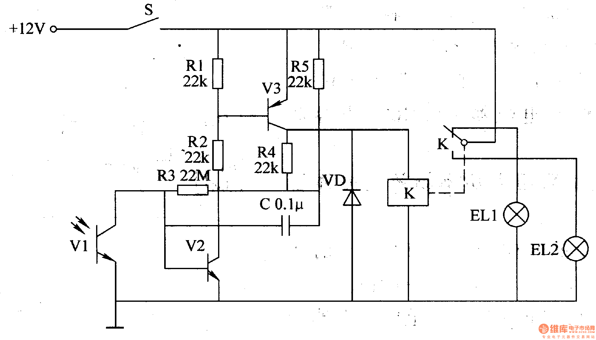
The working principle.The vehicle headlight auto-dimming controller circuit consists of phototransistor Vl, transistors V2 and V3, resistor Rl-R5, capacitor C, diode VD and relay K, the circuit is shown as the figure 7-9.
S is headlamp switch of car, EL2 is the internallow beam light of headlamp, ELlis the high beam. V2 and V3forms a Schmitt trigger circuit.
When driving at night, turning on S, + l2V voltage is added to the high beam by the normally closed contact of S and K, so that the EL2 islit.
When meeting other cars, the light exposure from the opposite traveling car will make the conduction ability of V1and V2 increase, V3 turns on, K gets power and pulls in, the normally open contact isconnected, high beam ELl turns off,low beamEL2 turns on.
After meeting cars, the internal resistance of V1 will increaseas it has no light exposure,the conduction ability of V2 decreases, V3 is cut off, K releases, the normally closed contact is connected, normally open contact is disconnected, ELl turns on,low beamEL2 turns off.
C is a positive feedback circuit, which makes Schmitt trigger circuit delay.
R1-R5 choose 1/4W metal film resistors or carbon film resistors.
C chooses monolithic capacitors or polyester capacitor.
VD uses lN4007 silicon rectifier diode.
K selects a l2V 4098 DC relay.
Reprinted Url Of This Article:
http://www.seekic.com/circuit_diagram/Control_Circuit/Light_Control/The_motor_vehicle_headlight_auto_dimming_controller_9.html
Print this Page | Comments | Reading(3)

Article Categories
power supply circuit
Amplifier Circuit
Basic Circuit
LED and Light Circuit
Sensor Circuit
Signal Processing
Electrical Equipment Circuit
Control Circuit
Remote Control Circuit
A/D-D/A Converter Circuit
Audio Circuit
Measuring and Test Circuit
Communication Circuit
Computer-Related Circuit
555 Circuit
Automotive Circuit
Repairing Circuit
Code: