
Light Control
Index
Online on the application of photoelectric control circuit diagram
Published:2014/1/24 23:04:00 Author: | Keyword: Online on the application of photoelectric control circuit diagram,
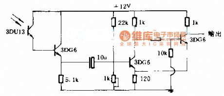
Online on the application of photoelectric control circuit diagram
(View)
View full Circuit Diagram | Comments | Reading(998)
Fine wire used for lighting control circuit diagram
Published:2014/1/24 21:54:00 Author: | Keyword: Fine wire used for lighting control circuit diagram,
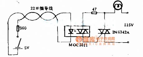
Fine wire used for lighting control circuit diagram
(View)
View full Circuit Diagram | Comments | Reading(939)
LD168 audio voltage-controlled flasher decorationcontrol circuit
Published:2012/11/7 19:25:00 Author:Ecco | Keyword: audio , voltage-controlled flasher, decorationcontrol circuit
In the figure, LD168 is a tape recorders flasher ASIC for speaker sound level indication. It has four outputs which can directly drive a plurality of light-emitting diodes, and it can also drive lantern light emitting SCR devices.
(View)
View full Circuit Diagram | Comments | Reading(808)
Acousto-optic control lantern with music sound circuit using SH805
Published:2012/9/19 2:18:00 Author:Ecco | Keyword: Acousto-optic control lantern , music sound circuit
As shown in the figure, the circuit consists of voice switch, light control switch, monostable timing circuit lantern control circuit and music sound circuit. The lamp control circuit has 16 functions of program which can automatically transform colorful light, and its control method is sound and light double control, and it won't be lit during the day, and lit at night. When the the lantern flashes, it is also accompanied by the melodious waltz music.
(View)
View full Circuit Diagram | Comments | Reading(871)
The voice control flowing Lantern associated with many famous songs circuit ( 5G167 )
Published:2012/9/18 1:42:00 Author:Ecco | Keyword: voice control , flowing Lantern , many famous songs
As shown in the figure, the circuit consists of acoustic / electric sensor, audio amplifier, ring count pulse distribution / driver circuit, SCR control circuit, songs sound circuit, audio amplifier circuit and AC buck rectifier circuit. IC1 uses 5G167, it is designed for ring count pulse distribution / driver ICs used in tape recorders rotary flash box, it contains the signal rectifier amplifier, voltage controlled oscillator and 3-bit ring timing counter and 3 drain output circuits and so on.
(View)
View full Circuit Diagram | Comments | Reading(833)
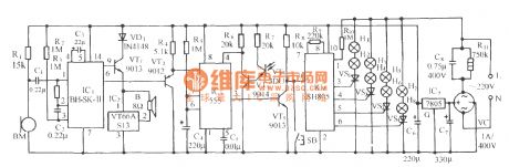
Acousto-Optic dual-controlled high - power lantern accompanied by birdsong circuit using SH805
Published:2012/9/13 2:02:00 Author:Ecco | Keyword: Acousto-Optic, dual- controlled , high - power , lantern , accompanied by birdsong
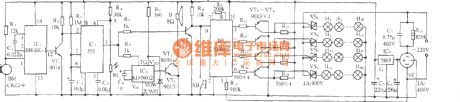
As shown in the diagram, the circuit consists of voice control circuit, Acousto-Optic dual control monostable timing circuit, SH805 lighting control circuit, birdsong voice circuit and AC buck rectifier circuit and other components. It can realize manual or automatic control of four high-power lantern with 16 kinds lantern patterns changing, but also sending sweet birdsong. BM is sound energy sensor; BH-SK-I is the voice control ASIC.
(View)
View full Circuit Diagram | Comments | Reading(818)
2D lamp controller
Published:2012/7/25 2:59:00 Author:Ecco | Keyword: 2D lamp , controller
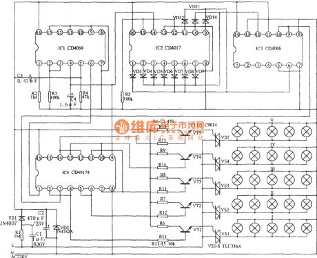
As shown in the figure, the circuit is mainly composed of the NAND gate IC1 (CD4096), counting / timing distribution circuit IC2 (CD4017), analog electronic switch IC3 (CD4066) and D trigger IC4 (CD40174). The lamp controller can control five groups of Lanterns to be lit and extinguished progressively. If a certain number of lanterns are connected in combination, you can create a scene with color change on the plane. It is more rich and colorful than usually control the flowing of the color in a line.
(View)
View full Circuit Diagram | Comments | Reading(2345)
Light gradually, gradually eliminate type lamp dimmer circuit
Published:2011/4/24 1:18:00 Author:May | Keyword: lamp dimmer
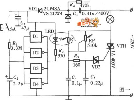
The diagram is lamp dimmer which has the function of light gradually, gradually eliminate. It does not appear the light stimulation of the human eye when the lights suddenly illuminated , and also can reduce the damage when open lamp impact current to the bulb, circuit is shown in the diagram. This circuit is LED driver circuit in optocoupler which consists of a six inverter circuit, in order to add the driver ability of the circuit, four inverters are use in parallel.
(View)
View full Circuit Diagram | Comments | Reading(2156)
Division circuit with NE555
Published:2011/8/30 2:13:00 Author:Jessie | Keyword: Division
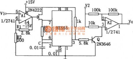
The circuit as shown is composedof thevoltage-frequency converterand amplitude modulator. Input V1 controls the resistance of mosfet 2N4222 by operational amplifier A1. Soit can change the oscillation frequency of no steady-state much harmonic oscillator. A2 is an input signal amplitude modulator. The input signal V2 is output after being modulated.It setsthe clip broken voltage of mosfetas Vp, if (1+R1/R2)=Vp, then the relationshipbetween output and input is: Vo=-V2/V1. The range of V1 and V2 is 0~10V. Output Vo is an average value, which can be gotten from filter or damping type voltmeter. (View)
View full Circuit Diagram | Comments | Reading(1392)
Operational amplifier precision zero circuit (REF200) diagram
Published:2011/8/30 2:36:00 Author:Jessie | Keyword: Operational amplifier, zero circuit
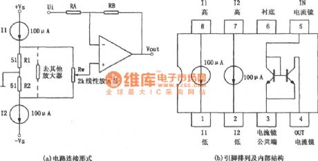
As shown in figure, the circuitis operational amplifier precision zero circuit. In some applications, it requires the disorder voltage of amplifierbeing small, and when the power supply voltage changes, thedisorder voltage is not affected. As shown in figure (a), the circuitcan realize this function. The circuit adopts double current source integrated chip REF200.The internal structure and pin arrangement of the chipare shown in figure (b). (View)
View full Circuit Diagram | Comments | Reading(1557)
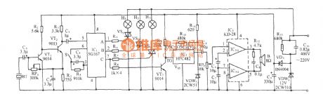
Slotted tip control photoelectric control circuit
Published:2011/12/1 1:09:00 Author:May | Keyword: Slotted tip control, photoelectric control
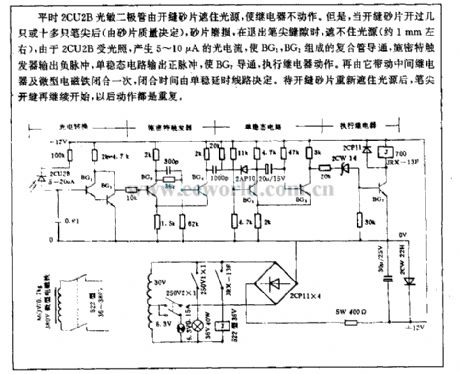
Usually, 2CU2B photosensitive diode shuts out light source by slitting carborundum discs tomake relay failure to actuate. But, when slitting carborundum discs is open byseveralor tens of nib ( the number depends on the quality of carborundum discs) , carborundum discs arefret, when itaborts nib, it can not shut out light source ( about 1mm), because 2CU2B has light, it can generate 5~10µA light curret to makeB1, BG2 compositive clad pipe breakover, Schmidt trigger output negative impulse, monostable circuit output positive impulse and BG7 breakover, execution relay action. Then it can drive middle relay and miniature solenoid close once, and theclosed time depends on monostable delay circuit. After slitting carborundum discs shut out light source again, nib slitting continue start, and the action repeats.
(View)
View full Circuit Diagram | Comments | Reading(1351)
Light control switch circuit adopts photoresistance LDR
Published:2011/11/10 1:03:00 Author:May | Keyword: Light control switch
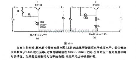
Whenthere isincoming ray, the transistor connected tothe photoresistor LDR in this circuitis inhigh level or zero level. Transistor magnification coefficient β>100 is enough, photoresistance is between 100Ω~100KΩ, which isseparately corresponding to light irradiation and dark situations. If you want to control the load with high power, you should adopt darlington transistors. (View)
View full Circuit Diagram | Comments | Reading(1696)
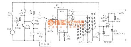
Coloured lamp control circuit composed of SH803
Published:2011/11/4 1:00:00 Author:May | Keyword: Coloured lamp, control circuit
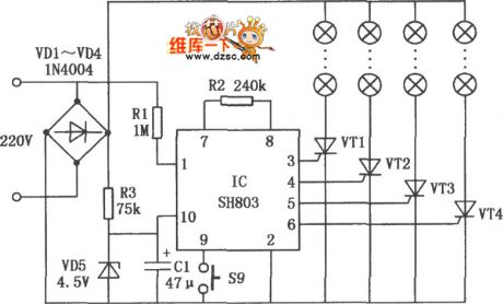
Coloured lamp control circuit composed of SH803 is shown in the diagram. It has eight functions, it can be realized by manual or automatic work, and it makeslight emitting diode or various coloured lampsgenerate varied and constantly changing flashing, so it is used for facade lighting decoration shop, holiday decorations and the motorcycle rear lights and brake lights and other decorations.
(View)
View full Circuit Diagram | Comments | Reading(1416)
Mood lantern controlling circuit (WT8089)
Published:2011/11/9 20:08:00 Author:May | Keyword: Mood lantern controlling
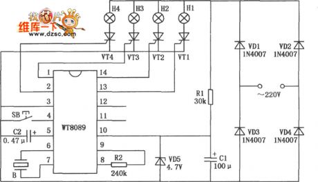
It can play eight electronic music and sixteent colorful light. Colorful flashing light and fine music can generate good audience effect. The jumping type of colorful light can becontrolled by function controlling buttons' pressing times to display sixteen different flashing kinds. They are turning right for horse racing, turning leftfor horse racing,turning on in the order, turning off in the order, double lights flowing moving, neighboring double light moving rolling, interval double lamps chasing, four lights flashing ar the same time, single lamp ordinal dithering, single lamp reverse dithering, double lights flashing, adjacent double lamps dithering chasing, double lamps reverse jitter flashing, interval double lamps jitter jumping, interval double lamps reverse jitter and four lights flashing and jitte.
(View)
View full Circuit Diagram | Comments | Reading(1477)
Six-way loop lantern control circuit composed of HFC3040
Published:2011/11/9 20:38:00 Author:May | Keyword: Six-way loop , lantern control
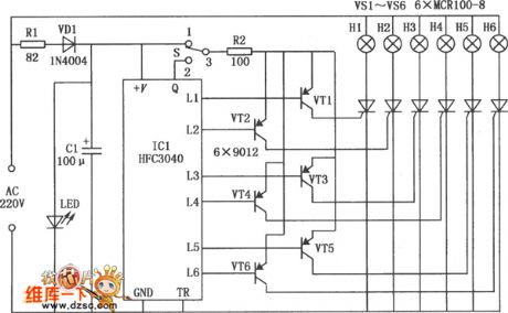
Six-way loop lantern control circuit composed of HFC3040 module can drive six-way lantern loop to flash, andit hastwo different loop speeds, and it is shown in the diagram. Because the circuit skillfully uses flashing integrated module HFC3040 to make circuit structure simple and cost low. IC1 is theflashing special integrate circuit HFC3040, and its working voltage range is 1.5~5V. So 220V ACvoltage is buck limited by R1, half-wave rectified byV1 to makeLED emit light. At the same time, the two ends ofLED 's about 1.6V steady DC voltageis filtered by C1 toofferpowerfor integrate circuit. Because TR's trigger ends connectto ground,it immediately is triggered to work after getting power. Six output ends L1~L6 is in low level orderly, so six PNP triodes VT1~VT6 are breakover orderly, unidirectional thyristors VS1~VS6and lanterns H1~H6 arelit one by one. (View)
View full Circuit Diagram | Comments | Reading(1068)
Voice controlling lamp (FC52) circuit
Published:2011/11/3 0:55:00 Author:May | Keyword: Voice controlling lamp
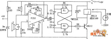
The diagram is voice controlling lamp circuit. This circuit consists of operational amplifier FC52, bi-stable flip-flop, relay J, piezoelectric crystal speaker y. The bi-stable flip-flop consists of double NAND gate TMY23A, when speaker y works, it can change voice signal to electric signal.
When clapping generates voice, Y will change voice signla to electric signal,then it will be added to opposite phase input end of FC52 to be enlarged. After enlarging, the output pulse isadded to bi-stable flip-flop. (View)
View full Circuit Diagram | Comments | Reading(1241)
The traffic light automatic controller circuit in traffic intersection
Published:2011/11/3 1:55:00 Author:May | Keyword: traffic light , automatic controller , traffic intersection
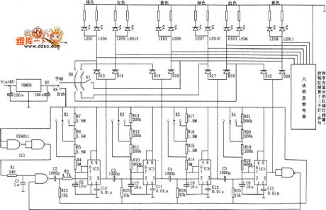
The input 8V voltage isregulated by78M05 to offer VDD=+5V power supply voltagefor 555.
Whenthe circuitgets power, the trigger pulse delaysby passingIC1 (CD4011) gate circuit and R1, C1,then it isadded to IC2's pin 2 after being differential by C2, R22, then the trigger IC2 outputs high level to be in transient state, and its transistion state timing time depends on K1's position, when delay td=1.1RC6, itsets time in 60s, 45s, 30s. When transient state finishes, IC2's pin 2 is inlow level, it isdifferential through C3, R23 to trigger IC3 and form second level signal-shot delay.
This circuit is monitor display part of control circuit. If it is really used to traffic command, it should use control signal to driver solid state relay, then the light bulb works. (View)
View full Circuit Diagram | Comments | Reading(2246)
Morning and evening light-operated switch circuit
Published:2011/11/23 21:07:00 Author:May | Keyword: light-operated switch, Morning and evening
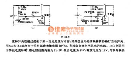
This kind of switch acts when it is above or below a cetrtain illumination, andits typical application is morming and evening street light auto switch. Diagram (a) and (b) show two circuits which adopt cadmium iodide photoresistor RPY20 directly supplied by AC electric fence. 1KΩ resistor isused to reducecurrent pulse. Relay coil 's essential resistance is 21.8Ω, and the pull-in voltage is 45V, release voltage is 18V. The capacitor connected with it in parallel makes up the RC with time constant in 0.1s, in order to minish the pulse DC voltage output by short-lived light flash and smoothness diode and prevent relay tremble, the relay touch point in diagram (a) circuit is normal closed. During the day,theillumination intensity is strong ( >31~45lx), thephotoresistance resistance is small, relay acts, andtouch point isopen, lamp goes out. At night, when illumination intensity is weak (<8.5~11lx) , on the contrary, the relay touch point in diagram (b) is normally open, its work is opposite from diagram (a). (View)
View full Circuit Diagram | Comments | Reading(1231)
Advertisement lamp automatic control circuit (555、CD4060)
Published:2011/11/4 1:27:00 Author:May | Keyword: Advertisement lamp automatic control
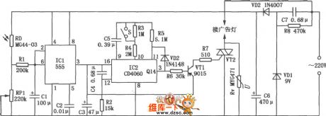
Most advertising lights have good publicity function only before 12 o 'clock at night, after midnight, pedestrian isscarce,then itloses theadvertising significance. This advertisement lamp automatic control circuit can connect power of advertising light brand automaticlly in the evening, at the same it starts timing, after 4 ~ 6 hours at midnight, it automatic cuts off power, so it realizes the automatic control and energy-saving purpose. The diagram is advertising light automatic control circuit, andit consists of power transformation, optical and timed components.
(View)
View full Circuit Diagram | Comments | Reading(1831)
Advertisement lamp automatic control circuit composed of 555、CD4060
Published:2011/4/23 9:07:00 Author:May | Keyword: Advertisement lamp automatic control
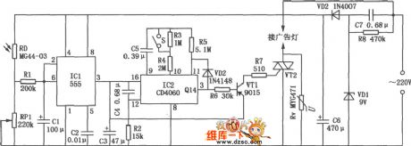
Most city advertising light have good publicity function only before night 12 o 'clock, after midnight, pedestrian scarce, also lost advertising significance. This advertisement lamp automatic control circuit can connect power of advertising light brand automaticlly in the evening when the day was black, at the same time it starts timing, after 4 ~ 6 hours at midnight automatic cut-off power, so as to realize the automatic control and energy-saving purpose. As shown in the diagram is advertising light automatic control circuit, it consists of power transformation, optical and timed components.
(View)
View full Circuit Diagram | Comments | Reading(1588)
| Pages:1/5 12345 |
Circuit Categories
power supply circuit
Amplifier Circuit
Basic Circuit
LED and Light Circuit
Sensor Circuit
Signal Processing
Electrical Equipment Circuit
Control Circuit
Remote Control Circuit
A/D-D/A Converter Circuit
Audio Circuit
Measuring and Test Circuit
Communication Circuit
Computer-Related Circuit
555 Circuit
Automotive Circuit
Repairing Circuit