
Light Control
Index 5
4302 Division circuit
Published:2011/4/14 20:35:00 Author:Jessie | Keyword: 4302 Division
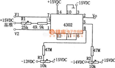
As shownis the division circuit composed by integrated block 4302, the inputs are V1 and V2, its output Vo is: Vo=10V1/V2. The input signal range: 0.03V≤V1≤10V, 0.03V≤V2≤10V. The circuit's typical error is ±25mV at 25℃, the max error is ±50mV, and output voltage accuracy affected by temperature, its temperature coefficient is ±1mV/C, output disorders voltage is 士10mV at 25℃, temperature coefficient is ±lmV/C. V1, V2's bandwidth in small signal is 500 kHzin small signal (-3dB), full range output is 60kHz. The adjustment method ofR1, R2 and R3 is: when V1=V2=+10V, adjust R1 to make the output Vo = +10V; When Vl=V2=+0.1V, adjust R2 to make output Vo=+10V; When V1=+0.01V, V2=+0.1V, adjust R3 to make Vo=+1V. So can adjust again and againfor a few times. (View)
View full Circuit Diagram | Comments | Reading(827)
MC1594 AC voltage multiplier circuit
Published:2011/4/14 22:02:00 Author:Jessie | Keyword: AC voltage, multiplier
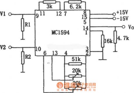
This circuit is composed by four quadrant multiplier MC1594, the circuit issimple, the accuracy is a bit poor. In order to make the circuit works in linear area, input resistance R1 and R2's values depend on the input voltage's value. R1 equals to V1 multiplied by 6, R2 equals to V2 multiplied by three. If V1=V2=3V, then R1=18kΩ, R2=9kΩ.When there aredifferent input voltages, generally R1=52kΩ, R2=30kΩ, but that would make precision and linearity fell. The relationship of input and output is Vo=V1V2/10. (View)
View full Circuit Diagram | Comments | Reading(1116)
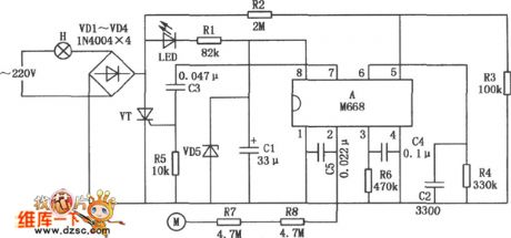
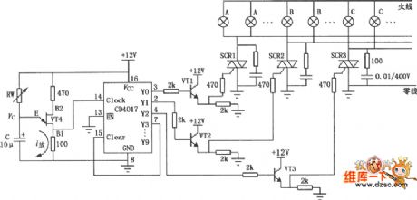
Family karaoke lighting control circuit composed of 5GM168
Published:2011/3/23 23:24:00 Author:may | Keyword: 5GM168
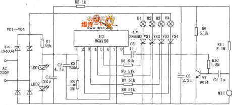
The design method of family karaoke lighting control is varied, here introduced control circuit is a application circuit with four load light ouput, jump circulate, speed controlable. Light jump speed change along with microphone received voice signal strong or weak, voice signal more strong, light jump faster, or speed is slow. Family karaoke lighting control circuit is shown in the diagram. This circuit mainly consists of power supply circuit, control circuit and audio-frequency amplifier.
(View)
View full Circuit Diagram | Comments | Reading(1223)
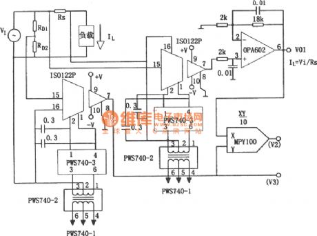
Power line load V, I and P isolation detection circuit
Published:2011/4/18 0:51:00 Author:Jessie | Keyword: Power line load V, I and P, isolation detection
View full Circuit Diagram | Comments | Reading(601)
Flash light control circuit composed of 556、CD4017
Published:2011/3/24 4:39:00 Author:may | Keyword: Flash light control
Flash light control circuit composed of 556、CD4017 is shown in the following diagram:
(View)
View full Circuit Diagram | Comments | Reading(1185)
Operational amplifier instrument circuit
Published:2011/4/13 22:55:00 Author:Jessie | Keyword: Operational amplifier, instrument
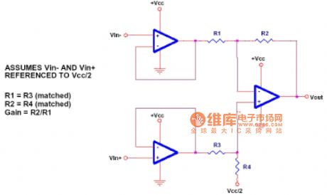
The circuit's gain is veryeasy tocalculate. But this circuit also has a weakness: that is in the circuit, the two resistances must be replaced together, and they must be equivalent. Another weakness is, the first level op-amp dose not produce any useful gain. (View)
View full Circuit Diagram | Comments | Reading(651)
Linear DC voltage multiplier circuit
Published:2011/4/14 2:15:00 Author:Jessie | Keyword: Linear, DC voltage, multiplier
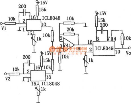
This circuit has two ICL8048 logarithmic amplifiers, ananti-logarithmic amplifier ICL8049, anda 741 op-amp. The relationship between output voltage andtwo input voltages is: Vo=V1V2/10. V1 and V2are +0.1 ~ +10VDC voltage. When the output voltageis +10V, its accuracyis 1%. (View)
View full Circuit Diagram | Comments | Reading(1234)
Operation amplifier phase buffer circuit
Published:2011/4/14 1:04:00 Author:Jessie | Keyword: Operation amplifier, phase buffer
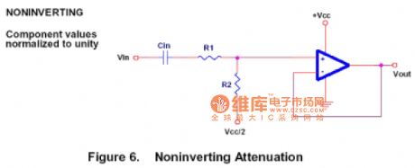
In figure, thein-phase attenuator can be used as a voltage attenuation and a in-phase buffer. (View)
View full Circuit Diagram | Comments | Reading(680)
Operation amplifier adder circuit
Published:2011/4/13 22:52:00 Author:Jessie | Keyword: Operation amplifier, adder

In figure, thereis an inverse adder,it is a basic audio mixer. But this circuit is rarely used in real audio mixer. Because it can approximate op-amp's work limit, actually we recommend increasing the supply voltage to improve dynamic range. In-phase addercan be realized, but is not recommended. Because the impedance of signal source will affect circuit's gain. (View)
View full Circuit Diagram | Comments | Reading(982)
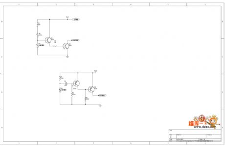
Light modulator receive circuit diagram
Published:2011/3/24 2:46:00 Author:Ecco | Keyword: Light modulator receive
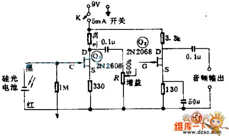
Q1, Q2 constitute of two class transistor amplifiers and used as zooming the modulating output semaphore of silicon solar battery. To 5lm/ft2 (lft=30.48 cms) beam of light modulated by 1000HZ, when the R is requlated to the biggest gain, the circuitry will produce 1V virtual value of voltage in output port.
Thiscircuitry issuitable foroptics correspondence andwarning system. (View)
View full Circuit Diagram | Comments | Reading(725)
Light control alarm circuit(For fire and night burglar alarm circuit)
Published:2011/4/12 22:40:00 Author:Ecco | Keyword: Light control, alarm circuit, fire alarm , night burglar alarm
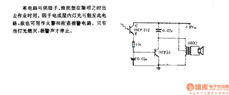
The circuit is available for hunters, fishermen when they want to go out at dawn. The flashlight or inside lights can trigger this circuit, it is also used as a fire and night burglar alarm circuit. Only when the lights turn off, the alarm can be stopped.
(View)
View full Circuit Diagram | Comments | Reading(616)
Timing light control circuit consist of CD4017
Published:2011/3/21 0:57:00 Author:may | Keyword: Timing light control
Timing light control circuit consist of CD4017 is show in the following diagram:
(View)
View full Circuit Diagram | Comments | Reading(1914)
Bi-directional thyristor dimmer circuit
Published:2011/3/25 1:15:00 Author:Jessie | Keyword: Bi-directional thyristor, dimmer
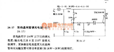
This circuit is used to adjust the brightness of the lamp below 200W, output voltage continuous stepless adjustment from 8 to 218 V. Replace thegreater rated current thyristor and bi-trigger tube can used in the higher power lamp.
(View)
View full Circuit Diagram | Comments | Reading(643)
Optically controlled circuitry diagram
Published:2011/3/20 22:55:00 Author:Ecco | Keyword: Optically controlled circuitry
Optically controlled circuitry diagram is as below:
(View)
View full Circuit Diagram | Comments | Reading(594)
Automatic dimming light circuit
Published:2011/3/21 1:49:00 Author:Joan | Keyword: Automatic dimming light, dimming light
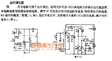
Lamp dimmer. The figure below shows the circuit can be used for lamp dimming. It uses a small quantity of components, which can be installed inside the lamp seat. The circuit is commonly used in RC phase shift circuit. W can be adjusted to change the triac conduction angle, which changes the lamp brightness. KS is a bi-directional trigger diode. C2 and L are anti-jamming devices. You can simplify the circuit if you do not ask more, such as reducing components, eliminating C2 and L2.
(View)
View full Circuit Diagram | Comments | Reading(1507)
Complementary dimming circuit
Published:2011/3/20 22:24:00 Author:Joan | Keyword: Complementary , dimming
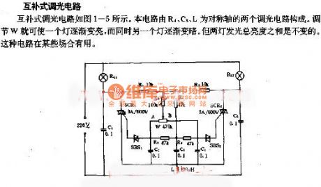
Complementary dimming circuitComplementary dimming circuit is shown in Figure 1-5, the circuit consists of two dimming circuit of which R1, C3, L are the axises of symmetry. W can be adjusted gradually to make a bright light, while the other light gradually dims. However, the total brightness of the two lamps is constant. This circuit is useful in certain situations.
(View)
View full Circuit Diagram | Comments | Reading(620)
| Pages:5/5 12345 |
Circuit Categories
power supply circuit
Amplifier Circuit
Basic Circuit
LED and Light Circuit
Sensor Circuit
Signal Processing
Electrical Equipment Circuit
Control Circuit
Remote Control Circuit
A/D-D/A Converter Circuit
Audio Circuit
Measuring and Test Circuit
Communication Circuit
Computer-Related Circuit
555 Circuit
Automotive Circuit
Repairing Circuit