Temperature Control
The circuit diagram of high Q notch filter
Published:2011/8/9 3:28:00 Author:Felicity | Keyword: high Q notch filter | From:SeekIC
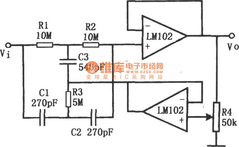
This figure shows the circuit of high Q notch filter. The operational amplifier in the low figure comprise voltage follower. The potentiometer R4 can change the value of Q (from 0.3 to 50). And the notch frequency : f0=1/2πR1C1. To avoid the drifting of f0, silvering mica or carbonate capacitor and matallic film resistance are needed. To reach 60dB attenuation, the allowance of resistance is below 0.1% ,and the allowance of capacity is below. To make LM102 work steadily, a 0.01μF capacitor is needed to filter the power.
Reprinted Url Of This Article:
http://www.seekic.com/circuit_diagram/Control_Circuit/Temperature_Control/The_circuit_diagram_of_high_Q_notch_filter.html
Print this Page | Comments | Reading(3)

Article Categories
power supply circuit
Amplifier Circuit
Basic Circuit
LED and Light Circuit
Sensor Circuit
Signal Processing
Electrical Equipment Circuit
Control Circuit
Remote Control Circuit
A/D-D/A Converter Circuit
Audio Circuit
Measuring and Test Circuit
Communication Circuit
Computer-Related Circuit
555 Circuit
Automotive Circuit
Repairing Circuit
Code: