
Temperature Control
Index
Rapid heating, cooling beverage thermostat machine
Published:2012/11/1 22:51:00 Author:Ecco | Keyword: Rapid heating, cooling beverage , thermostat machine
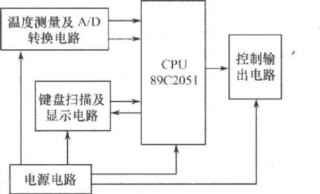

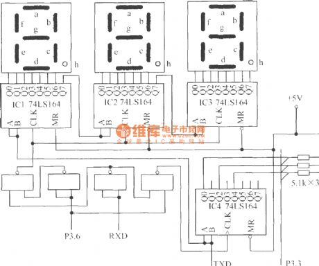

The hardware configuration of the thermostat machine system is composed of temperature measurement and A / D conversion circuit, signal testing and processing circuit, keyboard scan and display circuit, the control output circuit and power supply circuit. The system block diagram is shown below . ( 1 ) Signal testing and processing circuit: the core of the thermostat machine uses AT's cost-effective 8 - bit microcontroller AT89C2051, and it is used to complete the measurement and processing of the data and realize drinks temperature measurement and control function.
(View)
View full Circuit Diagram | Comments | Reading(1481)
Heatsink temperature monitor circuit
Published:2012/9/27 21:33:00 Author:muriel | Keyword: Heatsink, temperature monitor
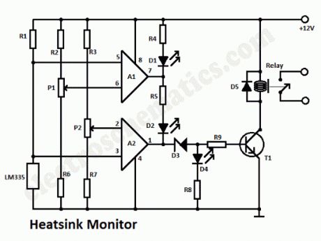
This heatsink temperature monitor circuit signals via 3 LEDs when the temperature exceeds 2 boundary levels. When the heatsink temperature is below 50 … 60oC (122 … 140oF) the greed LED lights. The yellow one signals that the temperature is within 60 and 70oC (140 … 158oF). The red one signals that the temperature has reached beyond 70 … 80o (158 … 176oF). At this point a relay can be triggered to break the power supply or otherwise protect the electronic device by turning ON a cooling fan.
As shown in the circuit diagram the heatsink monitor is made of 2 opamps that are set as window comparators. The input voltage level is set by the thermosensor IC LM335. This voltage level increses linearly by a factor of 10mV/oC. If this voltage is below the voltage level set by P1 and P2, the opamp outputs are almost at ground potential (0V) and the green LED lights up.
To set the desired temperature levels: put the thermosensor LM355 together with a thermometer into a pot of water which is being heated slowly. Turn P1 to its lowest point and turn P2 to its maximum. The switching point from green LED to yellow (50 … 60oC) is set with P1. The switching point from yellow to red is set withh P2. Watch thermometer while the water is being heated and adjust the potentiometers accordingly. Once the desired values are set, attach the thermosensor to the heatsink.
Heatsink Monitor circuit diagram
(View)
View full Circuit Diagram | Comments | Reading(2251)
Temperature controlled relay circuit
Published:2012/9/24 4:10:00 Author:muriel | Keyword: Temperature controlled, relay
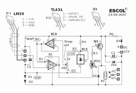
This temperature controlled relay circuit is a simple yet highly accurate thermal control circuit which can be used in applications where automatic temperature control is needed. The circuit switches a miniature relay ON or OFF according to the temperature detected by the single chip temperature sensor LM35DZ.When the LM35DZ detects a temperature higher than the preset level (set by VR1), the relay is actuated. When the temperature falls below the preset temperature, relay is de-energized. The circuit can be powered by any DC 12V supply or battery (100mA min.)
Electronic Temperature-Controlled Relay Schematic
How it works?The heart of the circuit is the LM35DZ temperature sensor which is factory-calibrated in the Celsius (or Centigrade) scale with a linear Degree->Volt conversion function. The output voltage (at pin 2) changes linearly with temperature from 0V (0oC) to 1000mV (100oC).
The preset (VR1) & resistor (R3) from a variable voltage divider which sets a reference voltage (Vref) form 0V ~ 1.62V. The op-amp (A2) buffers the reference voltage so as to avoid loading the divider network (VR1 & R3). The comparator (A1) compares the reference voltage Vref (set by VR1) with the output voltage of LM35DZ and decides whether to energize or de-energize the relay (LED1 ON or OFF respectively).
Source: http://www.escol.com.my/Projects/Project-03%28Thermostat-1%29/Proj-03.html
Components list:
IC1 : LM35DZIC2 : TL431IC3 : LM358
LED1 – 3mm or 5mm LED
Q1 – General purpose PNP transistor ( A1015,…) with E-C-B pin-out)D1, D2 — 1N4148D3, D4 — 1N400x (x=2,,,,.7)
ZD1 — Zener diode, 13V, 400mW
Preset (trim pot) : 2.2K (Temperature set point)R1 – 10KR2 – 4.7MR3 – 1.2KR4 – 1KR5 – 1KR6 – 33Ω
C1 – 0.1 μF ceramic or mylar capC2 – 470 μF or 680 μF electrolytic cap. (16V min)Miniature relay – DC12V DPDT, Coil = 400 Ω or higher ?
2 Responses to “Temperature controlled relay circuit”
(View)
View full Circuit Diagram | Comments | Reading(2153)
The barn ventilation cooling device circuit using TC626
Published:2012/9/19 2:02:00 Author:Ecco | Keyword: barn , ventilation, cooling device
As shown in Figure, the circuit consists of thermostat switch, thyristor control circuit, analog utterance circuit and AC buck rectifier circuit and other components. When the ambient temperature exceeds the set temperature, the circuit can be automatically ventilate and cooling with 3 sound animal sounds.
(View)
View full Circuit Diagram | Comments | Reading(1080)
The precious flower greenhouse thermostat control circuit with birdsong sound
Published:2012/9/19 3:36:00 Author:Ecco | Keyword: precious flower, greenhouse , thermostat control , birdsong sound
The circuit is shown as the figure. It consists of a temperature sensor, temperature control circuit, relay control heating circuit, birdsong sound circuit and AC buck rectifier circuit and other components. It enables flowers glasshouse to maintain the set temperature; when it is heating, it can also issue several crisp birdsong.
(View)
View full Circuit Diagram | Comments | Reading(1627)
Temperature monitor circuit
Published:2012/9/19 21:21:00 Author:Ecco | Keyword: Temperature monitor
This temperature monitor circuit is used where a continous analog display of temperature value being monitored is not necessary. A simple indication whether the temperature value exceeded a maximum level or went below the minimum level is sometimes enough. The circuit here does just that, it indicated the temperature level about +25oC (77oF) or below +20oC (68oF) by lighting one of the two LEDs. The temperature sensor is an NTC resistor coupled to two comparators. When D1 lights, the temperature is above +25oC and when D2 lights, the temperature is below +20oC.Temperature monitor calibration
Place the NTC resistor in cold water. Slowly heat the water until the desired maximum temperature level is reached, then adjust P1 until D2 lights up.
To set the minimum level, stop heating the water then slowly add cold water to it until the desired lower temperature level is reached as indicated by the thermomter. This time adjust P2 until D1 lights up.
Temperature level monitor circuit schematic
?
2 Responses to “Temperature monitor circuit”
Source: electroschematic.com (View)
View full Circuit Diagram | Comments | Reading(1202)
Kitchen Exhaust Fan Controlled by Temperature
Published:2012/9/19 21:19:00 Author:Ecco | Keyword: Kitchen Exhaust Fan, Controlled by Temperature
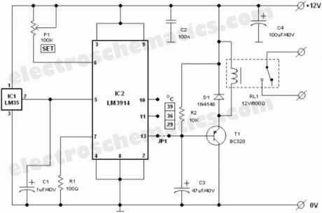
Exhaust fan is an important component in kitchens. Here is a simple circuit to control kitchen fans by monitoring the ambient temperature. It is built around the renowned precision integrated temperature sensor chip LM35 (IC1). Rest of the circuit is a non-traditional electromagnetic relay driver wired around the popular LED driver LM3914 (IC2). User can switch three presetted temperature levels using a jumper/slide switch (JP1), which determines the heat level to activate the relay and hence the electric exhaust fan wired through the relay contacts. It works off 12V DC power supply.
Kitchen Fan Controller Circuit Schematic
Only one adjustment is required in this kitchen exhaust fan controller circuit. After construction, set jumper point in its first position, ie base terminal of T1 is connected to pin 13 of IC2 and adjust the preset P1 carefully so that relay RL1 is energised when ambient temperature level reaches near 29oC. However this is not very critical as you can select any threshold level by connecting the jumper points to other unused output pins of IC2 (here only 3 outputs are used). More details about LM3914 and/or LM35 are available as pdf datasheet from NSC website.
Source: electroschematic.com (View)
View full Circuit Diagram | Comments | Reading(2172)
The overtemperature sprinkler cooling device circuit for menagerie building
Published:2012/9/17 1:44:00 Author:Ecco | Keyword: overtemperature sprinkler , cooling , menagerie building

The circuit is shown as the figure. It consists of temperature detecting circuit, voltage comparator circuit, power switch circuit, croak sound circuit, AC buck rectifier circuit and other components. When indoor temperature is more than 32℃ in summer, it can automatically start the sprinkler to cool temperature. When the room temperature falls below a predetermined temperature, it stops the sprinkler. The circuit is suitable for the breeding of rare birds and animals, the circuit is simple with reliable performance. When the sprinkler works, it also issued the acoustic sound of frogs calling to attract to the attention of the personnel on duty.
(View)
View full Circuit Diagram | Comments | Reading(994)
Automatic thermostat with birds sound circuit
Published:2012/9/14 2:04:00 Author:Ecco | Keyword: Automatic thermostat , birds sound
The circuit is shown in Figure, and it consists of thermal sensor head, monostable trigger circuit, birdsong sounding circuit and AC buck rectifier circuit. It enables the electric apparatus and the storage to keep in a set temperature range, when the temperature is lower than the minimum temperature because of the heat leaving from apparatus, the heater is automatically turned on for heating with several birdsong.
(View)
View full Circuit Diagram | Comments | Reading(1283)
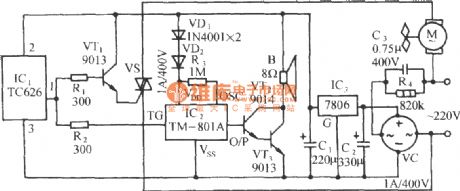
Computer room temperature control circuit using TC620 temperature sensor
Published:2012/9/13 1:44:00 Author:Ecco | Keyword: Computer room , temperature control , temperature sensor
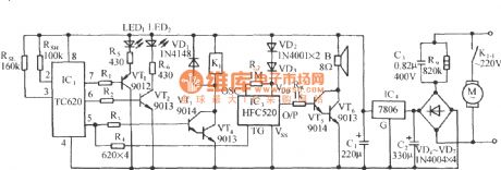
As shown in the figure, the circuit consists of the temperature sensor, control devices, the upper and lower temperature display, relay control motor circuit, waves analog voice circuit and AC buck rectifier circuit.
(View)
View full Circuit Diagram | Comments | Reading(1698)
Temperature Controller with U217B
Published:2012/9/12 21:09:00 Author:Ecco | Keyword: Temperature Controller
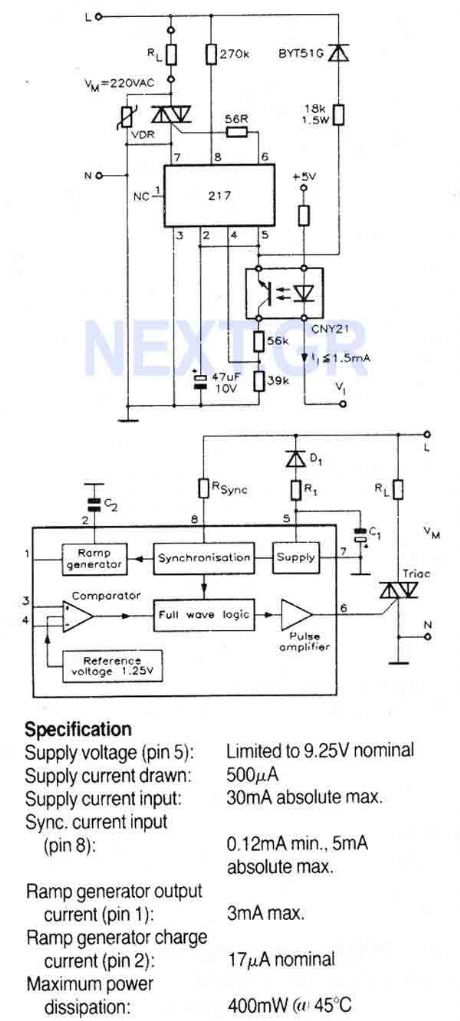
A triac controller for switching resistive loads directly from the mains supply using the zero crossing technique. The device is powered directly from the mains via a diode and dropper resistor, and the IC has its own regulator to limit its supply to 9.25V. To ensure that no switching occurs outside of the zero crossing point, full wave logic is employed to guarantee that complete mains cycles only are switched to the load.
Source: NEXT.GR (View)
View full Circuit Diagram | Comments | Reading(1615)
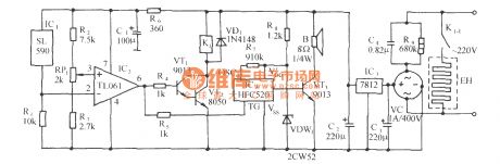
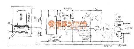
Thermostat schematic of thermistor electric water heater
Published:2012/8/16 22:27:00 Author:Ecco | Keyword: Thermostat schematic , thermistor, electric water heater
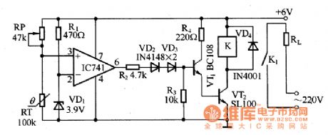
The circuit consistes of thermistor RT, comparator, driverand heater RL. The circuit can keep water temperature at 90 ℃ by automatically opening and closing control of the heater.
When temperature is at 25 ℃ thermistor resistance is 1OOkΩ, temperature coefficient of 1K / ℃. When comparator's inverting input end is added the 3.9V reference voltage, the comparator's noninverting input terminal is added the partial pressure voltage of RP and thermistor RT. When the water temperature belows 90 ℃, the comparator IC outputs high potential to drive VT1 and VT2 conduction, then the relay K works, heater circuit is closed; when the temperature is higher than 90 ℃, comparator IC output is in low potential, VT1 and VT2 are cut-off, the heater circuit is disconnected by relay K. Adjusting RP obtain the required water temperature.
(View)
View full Circuit Diagram | Comments | Reading(4242)
Eggs hatching incubator 2
Published:2011/10/18 3:45:00 Author:Ecco | Keyword: Eggs hatching incubator
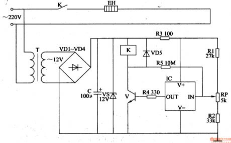
The eggs hatching incubator circuit is composed of the power supply circuit and temperature control circuit, and it is shown in Figure 4-5. Power supply circuit consists of the power transformer T, rectifier diodes VDl-VM, filter capacitor C and zener diode VS. Temperature control circuit consists of the resistors Rl-R5, potentiometer RP, diode VD5, temperature sensor integrated circuit IC, transistor V, Relay K and electric heater EH. Rl-R5 select the 1/4W metal film resistors or carbon film resistors. RP uses the small synthetic membrane potentiometer or multi-turn potentiometer. VDl-VD5 choose 1N4007 silicon rectifier diodes.
(View)
View full Circuit Diagram | Comments | Reading(3142)
The eggs hatching incubator circuit diagram 1
Published:2011/9/18 21:15:00 Author:Ecco | Keyword: Eggs hatching incubator
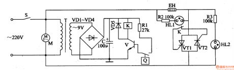
The eggs hatching incubator circuit is composed of the power supply circuit, temperature detection control circuit and indication circuit, and it is shown in Figure 4-4. Power supply circuit consists of the power switch S, power transformer T, rectifier diodes VDl-VD4 and filter capacitor C. Temperature detection control circuit consists of electric contact thermometer Q, resistor Rl, transistor V, Relay K, diode VD5, thyristors VT1, VT2, and the fan motor M. Indicating circuit consists of resistors R2, R3 and neon lights HLl, HL2. Rl-R3 select the 1/4W metal film resistors. C select the aluminum electrolytic capacitor with voltage in 25V.
(View)
View full Circuit Diagram | Comments | Reading(2121)
Electric oven temperature controller
Published:2011/8/9 20:14:00 Author:Ecco | Keyword: Electric oven , temperature controller

The electric oven temperature controller circuit is composed of the power supply circuit and temperature detection control circuit, and it is shown in Figure 3-80. Power supply circuit is composed of the power switch S, fuse FU, power transformer T, rectifier diodes VDl, VD2 and filter capacitor C. The temperature detection control circuit is composed of electric hot thermometer Q, relay K, diode VD3, resistors Rl, R2, Crystal thyristor VT, neon light HL and electric heater EH. Rl and R2 use the 1/4W carbon film resistors or metal film resistors. C selects the aluminum electrolytic capacitor with voltage in 25V. VDl-VD3 use the 1N4007 silicon rectifier diodes.
(View)
View full Circuit Diagram | Comments | Reading(4477)
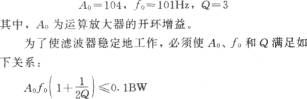
The Circuit Diagram of the 0.1~10Hz Filter (OP07)
Published:2011/8/12 4:51:00 Author:Felicity | Keyword: 0.1~10Hz Filter
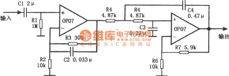
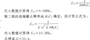
The figure shows the circuit diagram of the 0.1~10Hz filter. It’s composed of two parts. Part one is high-pass filter and part two is low-pass filter. The signal the frequency of which is above 0.1Hz can pass the first part and the signal the frequency of which is above 10Hz will be filtered out by the second part. And then the band-pass filtration is complete. The first part is non-inverting amplifier and the cutoff frequency depends on R1C1, as showed in the formula below: (View)
View full Circuit Diagram | Comments | Reading(2490)
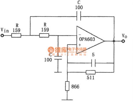
10MHz Band-Pass Filter Composed of OPA603
Published:2011/9/11 20:29:00 Author:Felicity | Keyword: 10MHz, Band-Pass, Filter
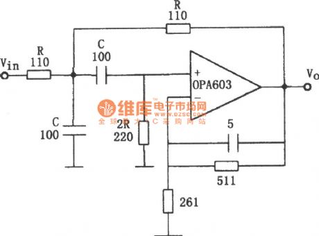
The circuit makes use of the Broadband Features high-speed current feedback op amp (G=1~10, the broadband reaches 100MHz). It makes the 10MHz pass filter. The parameter is showed in picture. (View)
View full Circuit Diagram | Comments | Reading(1410)
Language filter circuit
Published:2011/9/9 1:56:00 Author:John | Keyword: Language filter circuit
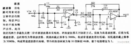
The circuit can be used to limit the language frequency band, which can remove interference and noise except the clatter. This function can be achieved by two multiple negative feedback with two second-order active filters. Two filters are set in a cascaded manner, whose pre-end is the high-pass filter and pro-end is the low-pass filter. The overall characteristics appear to be that of the band-pass filter. High-pass filter’s cutoff frequency is 300Hz, which can constitute the lower end of band-pass filter; and low-pass filter’s cutoff frequency is 3000Hz, which can constitute a higher end of band-pass filter. The rolling band’s attenuation is 40 dB per 10 octave and the circuit’s gain is 1.
(View)
View full Circuit Diagram | Comments | Reading(836)
The circuit diagram of the high gain band-pass filter (LM307) with low Q
Published:2011/8/12 4:54:00 Author:Felicity | Keyword: high gain, band-pass filter
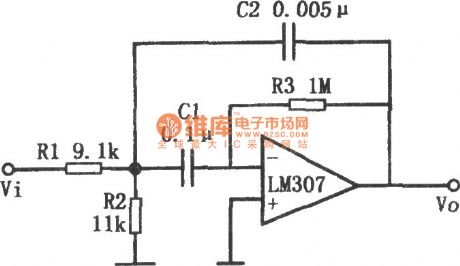
The circuit of the high gain band-pass filter with low Q is shown in this figure. Adding multiple feedback circuit to operational amplifier can build up a high gain band-pass active filter with low Q. This circuit adopts LM307 operational amplifier, using the components’ parameters in this figure to calculate: BW is the bandwidth when the gain of the operational amplifier is 1.
(View)
View full Circuit Diagram | Comments | Reading(1425)
OPA603 Constituted Low-pass Filter Circuit Of 10MHz
Published:2011/8/12 4:54:00 Author:Felicity | Keyword: Low-pass Filter, 10MHz
The circuit is showed in the picture. The circuit makes use of Second-order Butterworth low-pass filter. The fillter is made of high-speed current feedback operational amplifier OPA603 with broadband of 100MHZ. The transition frequency is f0=1/2πRC. The parameter is showed in the picture.f0=10MHz. Circuit gain is 1.6.
(View)
View full Circuit Diagram | Comments | Reading(1373)
| Pages:1/6 123456 |
Circuit Categories
power supply circuit
Amplifier Circuit
Basic Circuit
LED and Light Circuit
Sensor Circuit
Signal Processing
Electrical Equipment Circuit
Control Circuit
Remote Control Circuit
A/D-D/A Converter Circuit
Audio Circuit
Measuring and Test Circuit
Communication Circuit
Computer-Related Circuit
555 Circuit
Automotive Circuit
Repairing Circuit