
Temperature Control
Index 3
Distance isolation temperature analog circuit diagram
Published:2011/8/16 2:52:00 Author:Rebekka | Keyword: Distance isolation , temperature analog
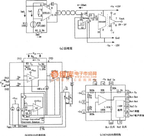

The figure shows the temperature analog circuit over long distances. In the practical application of the power system, the temperature of the equipment must be sent to the distance monitoring center, and it matchs with the measurement circuit, whichis isolated from the high voltage.In thecircuit, RTD is the platinum resistance temperature sensor, when the temperature rises, RTD resistance will be increased. The XTR101 has a high precision and WenPiao advantages, it can turn the temperature conversion into current signal, and it is easy to be transmitted over a long distance, because voltage signal in long-distance transmission loss error is large and vulnerable to electromagnetic interference.
(View)
View full Circuit Diagram | Comments | Reading(997)
Temperature controller circuit diagram 1
Published:2011/8/15 1:25:00 Author:Ecco | Keyword: Temperature controller
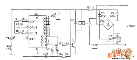
The intermittent controller circuit is composed of the power supply circuit, timer and control implementation circuit, and it is shown as the chart. Power supply circuit is composed of the capacitors C2 ~ C4, resistors R3 ~ R5, bridge rectifier UR, power regulator diode VS, and power indication light-emitting diode VL. The timer circuit is composed of counter / divider integrated circuit IC, capacitor C1, diodes VD2 ~ VD4 and resistors R1, R2, R6. R1, R2, C1 and IC internal circuit form the clock oscillator circuit, and the oscillation period (T) value is decided by R2 and C1. Control implementation circuit consists of the transistor V, resistor R7, diode VD1, AC contactor KM and relay K.
(View)
View full Circuit Diagram | Comments | Reading(905)
Temperature controller circuit diagram 6
Published:2011/8/15 21:44:00 Author:Ecco | Keyword: Temperature controller
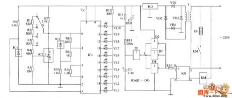
The temperature controller circuit is composed of the power supply circuit, temperature detection control circuit, LED indication circuit and heater control circuit, and it is shown as the chart. Power supply circuit is composed of the power transformer T, rectifier diodes VD1 ~ VD4, three-terminal voltage regulator integrated circuit IC5 and filter capacitor C1. Temperature detection control circuit is composed of the temperature sensor integrated circuit IC1, temperature control selector switch S, three-terminal voltage regulator integrated circuit IC2 and the resistors R1 ~ R6. LED temperature indicator circuit is composed of the voltage reference integrated circuit IC3, LED display driver integrated circuit IC4, resistors R8 ~ R13 and LEDs VL1 ~ VL10.
(View)
View full Circuit Diagram | Comments | Reading(1750)
Eggs hatching incubator circuit diagram 4
Published:2011/8/10 2:18:00 Author:Ecco | Keyword: Eggs hatching incubator
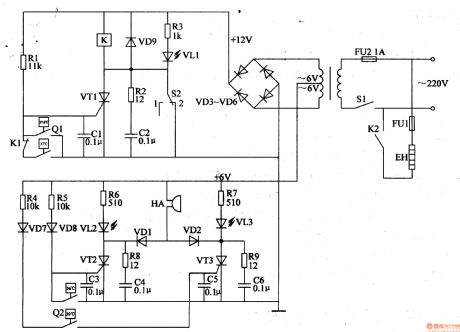
The eggs hatch incubator circuit is composed of the power supply circuit, constant temperature control circuit and sound and light alarm circuit, and it is shown in Figure 4-7. Power supply circuit consists of the power switch Sl, fuse FU2, power transformer T and rectifier diodes VD3-VD6. Temperature control circuit consists of the electric contact thermometer Ql, resistors Rl-R3, capacitors Cl, C2, thyristor VTl, diode VD9, relay K, light-emitting diodes VLl and manual / automatic switch S2. Sound and light alarm circuit consists of the electric contact thermometer Q2, resistors R4-Rg, capacitors C3-C6, transistors VT2, VT3, diodes VDl, VD2, VD7, VD8, light-emitting diodes VL2, VL3 and buzzer HA.
(View)
View full Circuit Diagram | Comments | Reading(5570)
Eggs hatching incubator 3
Published:2011/8/10 2:23:00 Author:Ecco | Keyword: Eggs hatching incubator
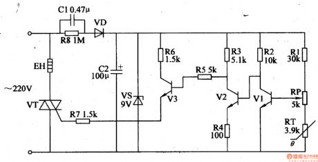
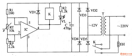
The eggs hatch incubator circuit is composed of the power supply circuit and temperature control circuit, and it is shown in Figure 4-6. The power supply circuit consists of the step-down capacitor Cl, discharge resistor R8, rectifier diode VD, filter capacitor C2 and zener diode VS. Temperature control circuit consists of the resistors Rl- R7, potentiometer RP, thermistor RT, transistor VT and thyristors Vl-V3. Rl-R8 select the 1/4W metal film resistors or carbon film resistors. RT uses the negative temperature coefficient thermistor. RP uses synthetic membrane potential, or precision multi-turn potentiometer.
(View)
View full Circuit Diagram | Comments | Reading(1488)
Remote Temperature-Measurement Circuit Composed Of Intelligent Remote Thermal Fan Controller ADT7460
Published:2011/7/14 10:10:00 Author:Robert | Keyword: Remote, Temperature-Measurement, Intelligent, Thermal, Fan, Controller
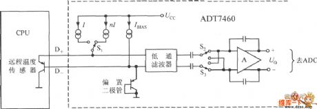
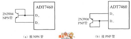
The remote temperature sensor is composed of ADT7460 with two transistors. As the transistor's emitter voltage is proportional to temperature, this feature could be used to measure the remote temperature. The remote temperature measurement circuit is shown in the picture. The CPU shown in the picture has the temperature-measurement transistor itself. It is equivalent to a 2N3906 PNP transistor. If using the discrete transistor, the collector polar can not be connected to ground and it should be connected to the base polar to be used as diode. If using the NPN transistor, it should connect the base polar to the D+ port, and connect the emitter polar to the D- port. If using the PNP transistor, it should connected the emitter polar to D+ port and connected the base polar to the D- polar. The picture shows the 2N3904 type NPN transistor and 2N3906 type PNP transistor's wiring mode. (View)
View full Circuit Diagram | Comments | Reading(815)
The Circuit Diagram of Q-adjustable Band-stop Filter (741)
Published:2011/8/8 21:43:00 Author:Felicity | Keyword: Band-stop Filter , Q-adjustable
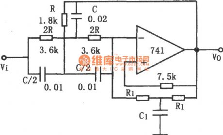
The notch frequency and the stability of Q depend on the passive components in the T-network. Appropriate components can make up a stable filter in this way. To build up a notch filter of high stability, passive components of high precision is needed besides high-performance operational amplifier. If R and C have the opposite temperature coefficient and R1, R have the same temperature coefficient, ω0 and Q are stable. (View)
View full Circuit Diagram | Comments | Reading(2077)
The circuit diagram of 8 order low-pass filter (MAX291,TA7504P)
Published:2011/8/8 21:46:00 Author:Felicity | Keyword: 8 order, low-pass filter
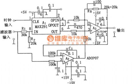
8 order low-pass filter circuit is shown in the figure. This circuit is 8 order low-pass filter circuit adopting switched-capacitor. Changing the clock frequency can change the cutoff frequency and the cutoff frequency is 1/100 of the clock frequency. +5V voltage square wave signal is put on the input terminal of the clock and then between input (IN) and output (OUT) terminal of A1 would get the performance of low-pass filter. Because of the input attenuator and the output amplifier, the input and output signal voltage can be ±10V.
(View)
View full Circuit Diagram | Comments | Reading(1502)
OPA2604 Constituted Third Order Low-pass Filter Circuit
Published:2011/8/6 8:46:00 Author:Felicity | Keyword: Third Order, Low-pass Filter
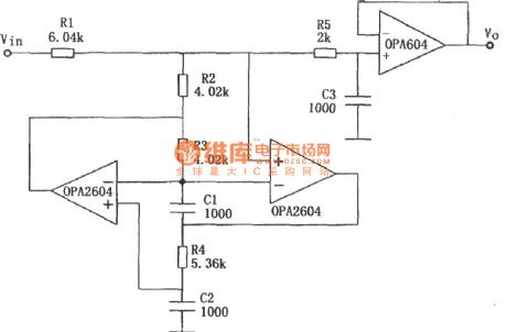
The circuit is showed in the piture above. The circuit makes use of a JFET-inputhigh-fidelityoperational amplifierOPA604 and a dualop ampOPA2604componentthird orderButterworthlow-pass filter. The parameter is showed in the picture. The cutoff frequency of-3dB is 40 KHz. (View)
View full Circuit Diagram | Comments | Reading(806)
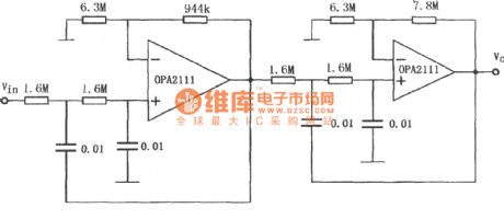
The circuit diagram of fourth-order Butterworth 10Hz low-pass filter consists of OPA2111
Published:2011/8/8 21:42:00 Author:Felicity | Keyword: fourth-order, Butterworth, low-pass filter
(View)
View full Circuit Diagram | Comments | Reading(1544)
The Circuit Diagram of 60Hz Notch Filter Consist of INA110
Published:2011/8/8 21:42:00 Author:Felicity | Keyword: Notch Filter, 60Hz
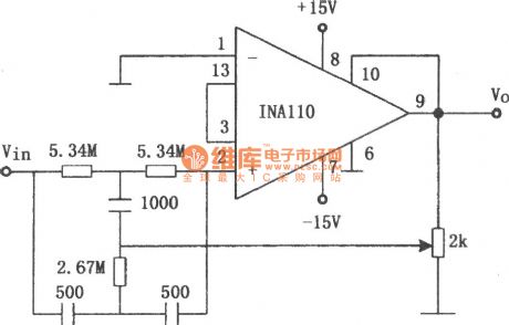
The figure shows the 60Hz notch filter consist of INA110 and double-T network. The 2kΩ potentiometer can adjust Q in this circuit. When the frequency of the city electricity is 50Hz, the resistance of this filter need to be changed, 5.34MΩ into 6.37MΩ and2.67MΩ into 3.16MΩ.This circuit can filter out the AC noise from the circuit. (View)
View full Circuit Diagram | Comments | Reading(1794)
The circuit diagram of frequency-adjustable band-pass filter (μA748)
Published:2011/8/9 2:40:00 Author:Felicity | Keyword: band-pass filter, frequency-adjustable
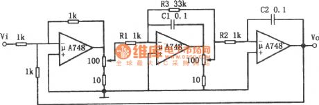
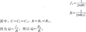
The resonant frequency of this filter can be adjusted by in-line potentiometer and Q can remain basically unchanged. Changing the position of the potentiometer is the same as adding a voltage divider. It can reduce the current that in R1, R2 and R3 which can be seen as increasing the resistance of R1, R2 and R3.As the potentiometer changed, the bandwidth and resonant frequency are also changed while Q remains basically unchanged. It’s because that the change of R1, R2, and R3 are the same. Changing the capacity of capacitor C1 can change the work frequency of the filter, but the adjustable extent of the bandwidth is not large. (View)
View full Circuit Diagram | Comments | Reading(1034)
The Circuit Diagram of 1 MHz High-pass Filter Consists of OPA603
Published:2011/8/8 7:54:00 Author:Felicity | Keyword: High-pass Filter
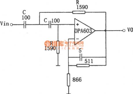
The figure shows the 1 MHz high-pass filter circuit. This circuit uses high speed current feedback operational amplifier OPA603 with 100MHz bandwidth and 1000V/μs slew rate. It is a second order Butterworth high-pass filter and the corner frequency f0=1/2πRC. Adopting the parameters shown in the figure, f0=1MHz and the circuit gain is 1.6. (View)
View full Circuit Diagram | Comments | Reading(1151)
The circuit diagram of notch filter consists of MC33171
Published:2011/8/8 6:51:00 Author:Felicity | Keyword: notch filter
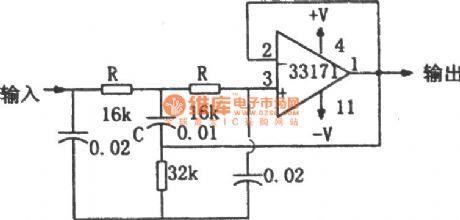
The figure shows the notch filter circuit. This circuit uses high-performance amplifier MC33171 to build up notch filter. This component has wide bandwidth and high switching rate. The notch frequency can be changed by adjusting the value of R and C: f=1/4πRC. (View)
View full Circuit Diagram | Comments | Reading(969)
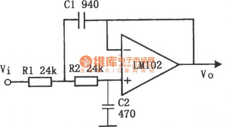
The Circuit Diagram of Active High-pass Filter (LM102)
Published:2011/8/8 11:29:00 Author:Felicity | Keyword: Active High-pass Filter

The figure shows the circuit diagram of active low-pass filter. The cutoff frequency fc=100Hz. In the circuit, the ratio of R1 to R2 or of C1 to C2 can be any value. In this circuit, R1=R2 and C1=2C2. C1=C2 and R1=2R2 can also be okay.
(View)
View full Circuit Diagram | Comments | Reading(2388)
The circuit diagram of active low-pass filter(LM102)
Published:2011/8/6 0:02:00 Author:Felicity | Keyword: active low-pass filter
The figure shows the circuit diagram of active low-pass filter (LM102).The cutoff frequency fc=10 kHz. In the circuit, the ratio of R1 to R2 or of C1 to C2 can be any value. In this circuit, R1=R2 and C1=C2. C1=C2 and R1=R2 can also be okay. (View)
View full Circuit Diagram | Comments | Reading(1998)
Electric blanket temperature controller circuit composed of Y982 module
Published:2011/8/4 21:49:00 Author:Rebekka | Keyword: Electric blanket, temperature controller
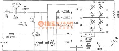
Y982 power adjustment module can be used for a variety of electric heater control. It can be used for the adjustment of the size of used appliances power. It has a timer function. It is an ideal transfer function devices. Electric blanket temperature controller circuit composed of Y982 module is shown as above. (View)
View full Circuit Diagram | Comments | Reading(3281)
Electric steam iron temperature controller
Published:2011/8/5 2:04:00 Author:Ecco | Keyword: Electric steam iron , temperature controller
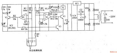
The electric steam iron temperature controller circuit is composed of the power supply circuit, water level detection circuit, temperature detection circuit and control implementation circuit, and it is shown in Figure 3-82. Power supply circuit is composed of the power transformer T, rectifier diodes VDl-VD4, resistor Rl, power indicator LED VLl, filter capacitors Cl-C4 and three-terminal voltage regulator integrated circuit ICl. Water detection circuit is composed of the the Nl which is inside of the operational amplifier integrated circuit IC2 (Nl, N2), transistor Vl, light-emitting diode VL2, resistors R2, R3, R5-R7, and the water level detection electrodes.
(View)
View full Circuit Diagram | Comments | Reading(4762)
Electric water heater temperature controller
Published:2011/8/5 2:08:00 Author:Ecco | Keyword: Electric water heater , temperature controller
The electric water heater temperature controller circuit is composed of the power supply circuit, leakage protection circuit, temperature control circuit, water level indication and anti-dry circuit, and it is shown in Figure 3-81. Power supply circuit is composed of the power transformer T, bridge rectifier UR, filter capacitors Cl, C2, and three-terminal voltage regulator integrated circuit ICl. Leakage protection circuit is composed of the current transformer TA, a time-base circuit which is inside of the dual time-base integrated circuit IC2 (lC2a, IC2b), and some other peripheral components. Temperature control circuit consists of the another time-base circuit which is inside of the dual time-base integrated circuit lC2, thermistor RT, transistor V, Relay K, potentiometer RP and the other external components.
(View)
View full Circuit Diagram | Comments | Reading(822)
Refrigerator temperature controller 2
Published:2011/8/5 2:56:00 Author:Ecco | Keyword: Refrigerator temperature controller
The refrigerator temperature controller circuit is composed of the power supply circuit and temperature detection control circuit, and it is shown in Figure 3-75. Temperature detection control circuit is composed of the thermistor RT, potentiometer RP, integrated electronic switch IC, resistors R1, R2, diode VDl, potentiometer K and working indicating LED VL. Power supply circuit is composed of the power transformer T, rectifier diode VL. Rl and R2 select 1/4W or 1/8W carbon film resistors. RP chooses the linear (X-type) potentiometer. C selects the aluminum electrolytic capacitor with the voltage in 16V. RT uses MF5l negative temperature coefficient thermistor. VDl-VD5 choose 1N4007 silicon rectifier diodes.
(View)
View full Circuit Diagram | Comments | Reading(2499)
| Pages:3/6 123456 |
Circuit Categories
power supply circuit
Amplifier Circuit
Basic Circuit
LED and Light Circuit
Sensor Circuit
Signal Processing
Electrical Equipment Circuit
Control Circuit
Remote Control Circuit
A/D-D/A Converter Circuit
Audio Circuit
Measuring and Test Circuit
Communication Circuit
Computer-Related Circuit
555 Circuit
Automotive Circuit
Repairing Circuit