
Temperature Control
Index 4
Refrigerator temperature controller 1
Published:2011/8/5 2:52:00 Author:Ecco | Keyword: Refrigerator temperature controller
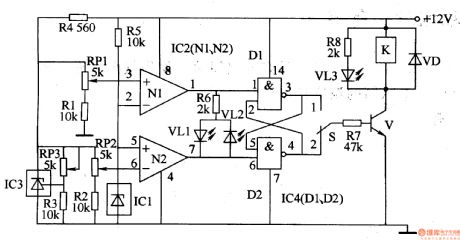
The refrigerator temperature controller circuit is composed of the temperature detection circuit, trigger and control implementation circuit, and it is shown in Figure 3-74. Temperature detection circuit consists of precision voltage regulator integrated circuit lC3, temperature sensor integrated circuit ICl, operational amplifier integrated circuit IC2 and resistors Rl-R5, potentiometers RPl-RP3. Trigger is composed of AND gate integrated circuit lC4, resistor R6 and light-emitting diodes VLl, VL2. Control implementation circuit is composed of the transistor V, heating / cooling control selector switch S, resistors R7, R8, relay K, light-emitting diodes VL3 and diode VD.
(View)
View full Circuit Diagram | Comments | Reading(1967)
The temperature controller 4
Published:2011/8/5 2:24:00 Author:Ecco | Keyword: temperature controller
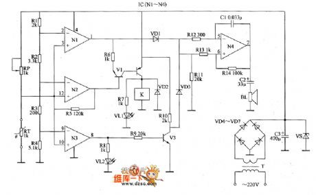
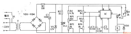
The temperature controller circuit is composed of the power supply circuit, the temperature detection control circuit and over-temperature alarm circuit, and it is shown as the chart. Power supply circuit is composed of the power transformer T, rectifier diodes VD4 ~ VD7, filter capacitor C3 and Zener VS. Temperature detection control circuit consists of the N1 ~ N3 which are inside of four operational amplifier integrated circuit IC (M ~ N4), resistors R1 ~ R1O, transistors V1 ~ V3, potentiometer RP, thermistor RT, LEDs VL1, VL2, diode VD2 and relay K. VD1 ~ VD3 select 1N4l48 silicon switching diodes; VD4 ~ VD7 select 1 N4007 silicon rectifier diodes.
(View)
View full Circuit Diagram | Comments | Reading(1008)
Using MAX1298/1299 To Make Up Temperature/Voltage Monitoring System Circuit
Published:2011/8/1 10:52:00 Author:Robert | Keyword: Temperature, Voltage, Monitoring, System
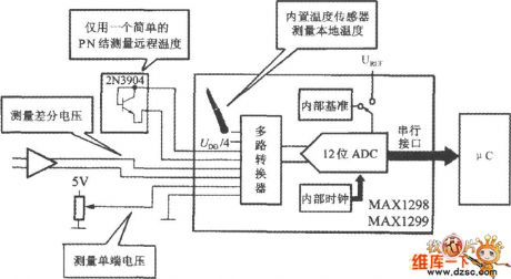
As shown in the picture. This system uses the internal temperature sensor to measure the room temperature. And it uses a 2N3904 type transistor's emitter polar to measure the remote temperature. Other input channels are used to measure the differencial voltage and 0~+5V single-port voltage. The MAX1298/1299 is connected to the uC through the serial interfaces. (View)
View full Circuit Diagram | Comments | Reading(564)
Celsius Temperature And Temperature Difference Measuring Circuit
Published:2011/7/26 21:21:00 Author:Robert | Keyword: Celsius, Temperature, Difference, Measuring
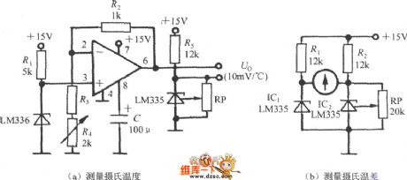
The LM135 series is based on the thermodynamic temperature calibration. If wanting to measure the celsius temperature (t) and celsius temperature difference (△t), it could use the circuits shown in picture (a) and (b). The picture (a)'s circuit's output port is connected to digital voltage meter and it would display the celsius temperature value. The picture (b)'s circuit is used to indicate the temperature difference by using galvanometer. (View)
View full Circuit Diagram | Comments | Reading(812)
Temperature controller circuit diagram 2
Published:2011/7/28 21:37:00 Author:Ecco | Keyword: Temperature controller
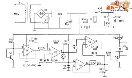
The temperature controller circuit is composed of the power supply circuit, temperature detection circuit, reference voltage circuit, temperature indicator circuit, voltage comparator amplifier and control implementation circuit, and it is shown as the chart. Power supply circuit is composed of the power switch S, power transformer T, bridge rectifier UR, filter capacitors C1, C2, three-terminal voltage regulator integrated circuit IC2, current limiting resistor RIO and power indicator LED VL1. Temperature detection circuit consists of the transistor temperature sensor V1, resistor R1, capacitor C3 and N1 which is inside of the operational amplifier integrated circuit IC1 (N1 ~ N4).
(View)
View full Circuit Diagram | Comments | Reading(1580)
Temperature controller circuit diagram 5
Published:2011/7/28 21:46:00 Author:Ecco | Keyword: Temperature controller
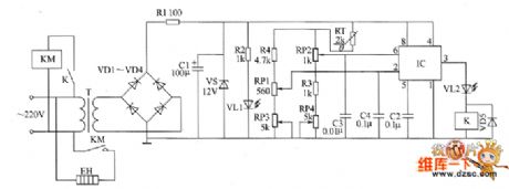
The temperature control circuit is composed of the power supply circuit, temperature detection control circuit and control implementation circuit, and it is shown as the chart. Power supply circuit is composed of the power transformer T, rectifier diodes VD1 ~ VD4, resistors R1 and R2, power indicator LED VL1, filter capacitor C1 and Zener VS and so on. Temperature detection control circuit consists of thermistor RT, time-base integrated circuit IC, potentiometers RP1 ~ RP4, resistor R3 and capacitors C2 ~ C4. Control implementation circuit is composed of the relay K1, LED VL2, diode VD5, AC contactor KM and electric heater EH.
(View)
View full Circuit Diagram | Comments | Reading(995)
Temperature controller circuit diagram 3
Published:2011/7/28 21:41:00 Author:Ecco | Keyword: Temperature controller
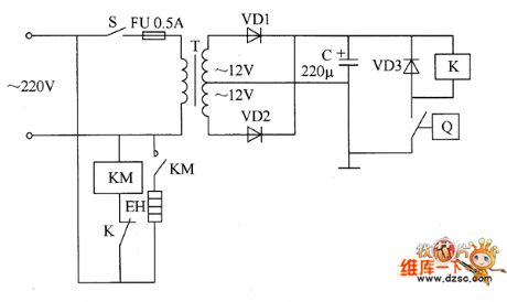
The temperature controller circuit is composed of the power supply circuit and temperature detection control circuit, and it is shown as the chart. Power supply circuit is composed of the power switch S, fuse FU, power transformer T, rectifier diodes VD1, VD2 and filter capacitor C. Temperature detection control circuit is composed of electric contact thermometer Q, relay K, AC contactor KM, diode VD3 and electric heater EH. C selects the aluminum electrolytic capacitor with the voltage in 25V. VD1 ~ VD3 select the 1 N4007 silicon rectifier diodes. K selects the JRX-13F orJQX-4F 12V DC relay.
(View)
View full Circuit Diagram | Comments | Reading(725)
Temperature controller circuit diagram 4
Published:2011/7/28 21:44:00 Author:Ecco | Keyword: Temperature controller
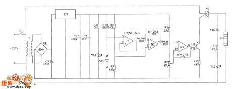
The temperature controller circuit is composed of the power supply circuit, temperature detection control circuit and control implementation circuit, and it is shown as the chart. Power supply circuit is composed of the power switch s, power transformer T, bridge rectifier UR, filter capacitors C1 ~ C3, three-terminal voltage regulator integrated circuit IC1, resistor R2 and power indicator LED VL1. Temperature detection control circuit is composed of the temperature detection diode VD1, resistors R3 ~ R1O, operational amplifier integrated circuit IC2 (N1 ~ N3) and the potentiometer RP. R1 ~ R12 select the 1/4W metal film resistors. RP uses a linear potentiometer. C1 selects the aluminum electrolytic capacitor with voltage in 25V.
(View)
View full Circuit Diagram | Comments | Reading(963)
Thermostat, governor diagram 2
Published:2011/6/26 21:02:00 Author:Nora | Keyword: Thermostat, governor , diagram
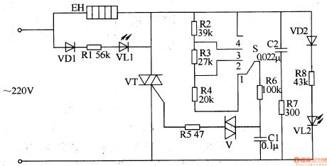
When the power selector adjust the switch S, it can change the capacitor charge and discharge rate of Cl, thus change the thyristor conduction angle. Cl through V to the voltage across the trigger and make it turn-VT, by changing the conduction angle of VT to change the electric heater EH (load) both ends of the AC voltage level. VLl and VL2 for the working status indicator LEDs. Placed in the S l stalls, VL2 light; the S placed in the 4 stalls, VLl light. (View)
View full Circuit Diagram | Comments | Reading(1021)
Breeze ceiling fan temperature controller circuit composed of the NE555
Published:2011/6/28 3:16:00 Author:Rebekka | Keyword: Breeze ceiling fan, temperature controller
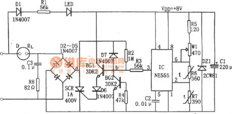
When environment temperature increases, the resistance of the corresponding R7 R6 become smaller and make the IC (2) feet down to less than a third potential VDD and it is reset, 3 feet output high level. So the controlled silicon AC zero-voltage switching composed of D2~D5、SCR、BG1、BG2 will be turned on. Fan D operates when supply power is open; When the environment temperature falls, resistance of the corresponding R7, R6 changes, 555 is reset because the feet (2) is larger than a third potential VDD, (3) feet outputs low level, so that the controlled silicon AC zero-voltage switching is closed. The electric fan D stops because the power supply is closed. (View)
View full Circuit Diagram | Comments | Reading(1154)
The fermentation cylinder temperature alarm and controll circuit composed of the NE555
Published:2011/6/28 3:54:00 Author:Rebekka | Keyword: fermentation cylinder
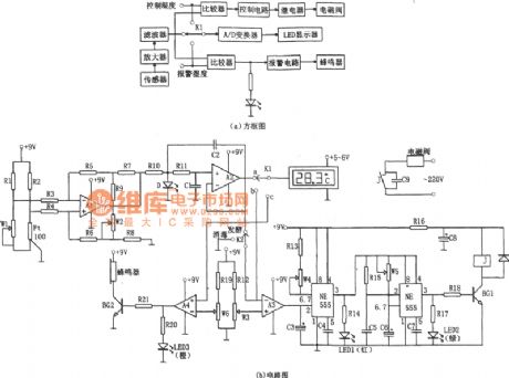
The alarming circuit is composed of comparator A4 and buzz circuit. When the temperature is more than 29 ℃, the A4 inverse end set potential compare with the A2 output. A4 outputs high level. The BG2 is conducted. It sounds bees alarm and at the same time the LED3 bright alarm lights (orange light) to remind the officer on duty to note out fault. It makes temperature control in the most suitable range. This circuit can make the temperature in 28 + 1 ℃, when the temperature is more than 29 ℃, the circuit will sound and light alarm signal to remind people. (View)
View full Circuit Diagram | Comments | Reading(724)
Temperature controller circuit diagarm 1
Published:2011/7/25 22:16:00 Author:Ecco | Keyword: Temperature controller
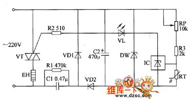
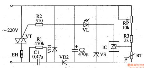
The power supply circuit is composed of the step-down capacitor C1, discharge resistor RI, rectifier diodes VD1, YD2, filter capacitor C2 and zener diode VS. Temperature detection control circuit is composed of the thermistor RT, resistors R2, R3, potentiometer RP, light-emitting diode YL, three-terminal precision regulator integrated circuit IC and thyristor VT. RI selects the l/2W metal film resistor: R2 and R3 select the l/4W metal film resistor. RP uses the multi-turn potentiometer. vs uses the 2DW7 silicon zener diode.
(View)
View full Circuit Diagram | Comments | Reading(713)
Temperature controller circuit diagarm 2
Published:2011/7/25 22:19:00 Author:Ecco | Keyword: Temperature controller
Power supply circuit is composed of the power switch s, fuse FU, power transformer T, rectifier diodes VD1 ~ VD4, filter capacitor C1 and three-terminal regulator integrated circuit IC1. Temperature detection control circuit is composed of the thermistor RT, voice control integrated circuit IC2, transistor V, relay K, capacitors C2, C3, resistors RI ~ R3 and LEDs YL1, VL2. RI uses the 1/4W carbon film resistor or metal film resistor; R2 and R3 select the 1/2W carbon film resistors.
(View)
View full Circuit Diagram | Comments | Reading(681)
Electric heating appliance temperature controller 1
Published:2011/7/26 2:40:00 Author:Ecco | Keyword: Electric heating appliance , temperature controller
The electric heating apparatus temperature control circuit is composed of the power supply circuit and temperature detection control circuit, and it is shown in Figure 3-76. Rl selects the 1/2W metal film resistor; R2 and R3 select 1/4W metal film resistors. RP uses the multi-turn potentiometer. RT uses NTC502 negative temperature coefficient thermistor, and the room temperature (25 ℃) resistance is about 5kΩ. Cl uses the polyester capacitor or CBB capacitor with voltage being greater than 400V; C2 select the aluminum electrolytic capacitor with voltage in 16V. VDl, VD2 choose the 1N4007 silicon rectifier diode.
(View)
View full Circuit Diagram | Comments | Reading(743)
Electric heating appliance temperature controller 2
Published:2011/7/26 2:42:00 Author:Ecco | Keyword: Electric heating appliance, temperature controller
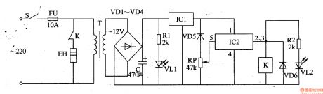
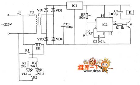
The electric heating apparatus temperature controller circuit is composed of the power supply circuit and temperature detection control circuit, and it is shown in Figure 3-77. Power supply circuit is composed of the power switch S, fuse FU, power transformer T, rectifier diodes VDl-VM, filter capacitor C, three-terminal voltage regulator integrated circuit ICl, current limiting resistor Rl and the power indicator LED VLl. Temperature detection control circuit is composed of the temperature sensing diode VD5, potentiometer RP, electronic switch integrated circuit IC2, relay K, diode VD6, resistor, saturated light-emitting diode VL2.
(View)
View full Circuit Diagram | Comments | Reading(647)
Electric heating appliance temperature controller 4
Published:2011/7/26 2:48:00 Author:Ecco | Keyword: Electric heating appliance , temperature controller
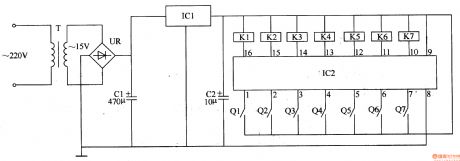
The electric heating apparatus temperature controller circuit is composed of the power supply circuit and temperature detection control circuit, and it is shown in Figure 3-79. Power supply circuit is composed of the power transformer T, bridge rectifier UR, filter capacitors Cl, C2, and three-terminal voltage regulator integrated circuit ICl. Temperature measurement control circuit consists of seven-segment LED digital integrated circuit IC2 and electric hot thermometers Ql-Q7, relays Kl-K7. Cl and C2 select the aluminum electrolytic capacitors with voltage in 25V.
(View)
View full Circuit Diagram | Comments | Reading(648)
Electric heating appliance temperature controller 3
Published:2011/7/26 2:45:00 Author:Ecco | Keyword: Electric heating appliance, temperature controller
The electric heating apparatus temperature controller circuit is composed of the power supply circuit and temperature detection control circuit, and it is shown in Figure 3-78. Power supply circuit is composed of the power transformer T, rectifier diodes VD1-VD4, resistor B1, power indicator LED VL1, filter capacitor C1 and Zener VS. Temperature detection control circuit consists of thermistor RT, time-base integrated circuit IC, potentiometers RPl, RP2, resistors R2, R4, capacitors C2-C4, relay K1, diode VD5 and light-emitting diode VL2.
(View)
View full Circuit Diagram | Comments | Reading(721)
Temperature Compensation Circuit
Published:2011/7/11 6:07:00 Author:Robert | Keyword: Temperature, Compensation
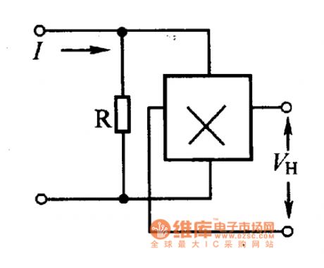
The error caused by the temperature could be compensated by the method of using parallel resistances. Its calculated formula is R=βRin/α.β. The Rin could be found in the parameter table. Its specific circuit is shown in the picture.
The picture shows the temperature compensation circuit. (View)
View full Circuit Diagram | Comments | Reading(617)
Temperature Control Circuit of Transistor Temperature Sensor
Published:2011/7/7 15:54:00 Author:Michel | Keyword: Transistor, Temperature Sensor, Temperature Control Circuit
This picture is temperature control circuit of transistor temperature sensor.In this circuit,the voltage and tempreature between the base and emitter is inversely proportional.RP2, R3 ,r4-g9 and it consititute bridge road together.A1 amplifies the unbalanced voltage of the bridge road.A1 outputs 100 mV votlage u when the temperature changes 1 ℃.Please adjust RP2 and when the temperature is 0℃,A1 outputs 0V.Please adjust RP2 and when the temperature is 1℃,A1 outputs 100mV. (View)
View full Circuit Diagram | Comments | Reading(701)
Temperature PID Control Circuit of Operational Amplifier
Published:2011/6/22 6:41:00 Author:Michel | Keyword: Operational Amplifier, Temperature, PID Control Circuit
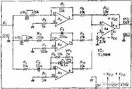
Error integral circuit can be added to the ordinary proportional control circuit if the temperature is controlled and it reaches specified value in the shortest time.But the error will increases as time goes on,the differentiating element is added to the circuit to reduce the error and increase speed and it make quick response to rapid changing temperature and the control is called PID contorl.This circuit form has high accuracy control and it is widely used.
Circuit's Work PrincipleP represents proporation circuit and it's relevant to loop gain.The variable resistance VR1 can change between 0.5~∞ by using the opposite phase the amplifier gain A.
(View)
View full Circuit Diagram | Comments | Reading(6482)
| Pages:4/6 123456 |
Circuit Categories
power supply circuit
Amplifier Circuit
Basic Circuit
LED and Light Circuit
Sensor Circuit
Signal Processing
Electrical Equipment Circuit
Control Circuit
Remote Control Circuit
A/D-D/A Converter Circuit
Audio Circuit
Measuring and Test Circuit
Communication Circuit
Computer-Related Circuit
555 Circuit
Automotive Circuit
Repairing Circuit