
Temperature Control
Index 5
The warm-up time and the charge(2LT type, 2L diesel engine) theory circuit of 70 light sport utility vehicle of Toyota Land Cruiser
Published:2011/6/26 4:31:00 Author:Sophia | Keyword: Warm-up time, Charge(2LT type, 2L diesel engine), theory circuit, 70 light sport utility vehicle of Toyota Land Cruiser
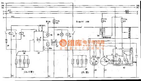
Off-road vehicles with a 2L-T type or 2L diesel engine, in general,fit the electric plug inside the cylinder. the glow plugs 35 is controlled by the relay 33, relay coil 33 is controlled by the warm-up timer 37. Warm-up timer work when plug 38a installed in the cooling system inputs the water temperature. When the water temperature is above 5 ℃, if the ignition switch is switched on, preeat indicator light will flash about 38 (about 0.3S), which means that can be started directly; if the water temperature is below 5 ℃, the preheat light 38 will stay on for an period of time (about 18S), until the temperature of warm-up plugs inside the cylinder reaches 800 ℃ or so and lights is off, which shows the vehicle can be started. 70 light-duty off-road vehicle also is equipped with emission control systems. When the water temperature is low, the fuel will have poor atomization, incomplete combustion production is excessive. Emission controller 46 will control the throttle idle switch electromagnetism valve 44, while make the cold mixture heater work and heat up atomization. (View)
View full Circuit Diagram | Comments | Reading(2564)
Active biquad low-pass filter circuit
Published:2011/7/7 0:01:00 Author:Fiona | Keyword: Active, biquad low-pass filter
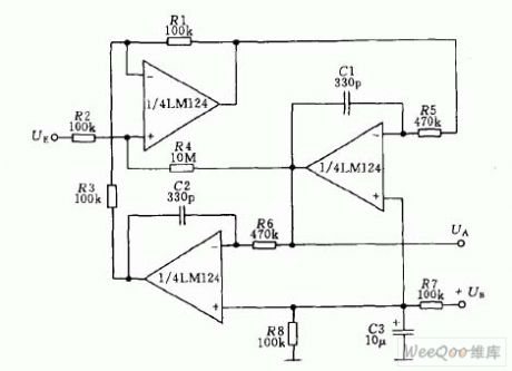
Active filter circuit is shown as above, its center frequency is1KHz, the quality factor Q = 50, gain KV = 100 (it's equal to 40dB)
(View)
View full Circuit Diagram | Comments | Reading(818)
Bean sprout machine thermostat controller circuit diagram
Published:2011/6/14 3:11:00 Author:Lucas | Keyword: Bean sprout machine, thermostat controller
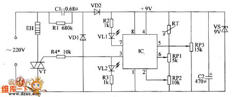
The bean sprout machine thermostat controller circuit is composed of the power supply circuit and temperature detection control circuit, and the circuit is shown as the chart. The power supply circuit is composed of the drain resistor R1, rectifier diodes VD1, VD2, power regulator diode VS, buck capacitor C1, filter capacitor C2. Temperature detection control circuit is composed of the thermistor RT, potentiometers RP1 ~ RP3, resistors R2 ~ R4, VT and heating wire EH. AC 220V voltage bucked by C1, rectified by VD1 and VD2, stabilized by VS and filtered by C2 can provide +9 V voltage for IC. R1 ~ R4 select 1/2W metal film resistors. RP1 ~ RP3 use synthetic membrane potentiometers. VD1 and VD2 select 1N4007 silicon rectifier diodes.
(View)
View full Circuit Diagram | Comments | Reading(2155)
Bean sprouts automatic watering thermostats circuit diagram
Published:2011/6/14 3:03:00 Author:Lucas | Keyword: Bean sprouts , automatic watering , thermostats
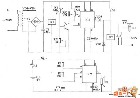
The bean sprouts automatic watering thermostats circuit is composed of the power supply circuit, temperature detection control circuit and power failure alarm circuit, and the circuit is shown as the chart. Temperature detection control circuit is composed of the thermistor RT, potentiometers RP1 ~ RP3, transistor V, time-base integrated circuit IC1 and capacitor C2, diodes VD5, VD6, relay K2 and the control switch S1 . Power failure alarm circuit consists of the relay K1, switch S2, resistors R1, R2, capacitors C3, C4, and speaker BL and the time-base integrated circuit IC2. R1 and R2 use 1/4W carbon film resistors or metal film resistors. RP1 ~ RP3 use small organic solid potentiometers or variable resistors. RT chooses the thermistor resistor with negative temperature coefficient.
(View)
View full Circuit Diagram | Comments | Reading(990)
Greenhouse ground hotline controller circuit diagram 1
Published:2011/6/14 5:15:00 Author:Lucas | Keyword: Greenhouse, ground hotline, controller
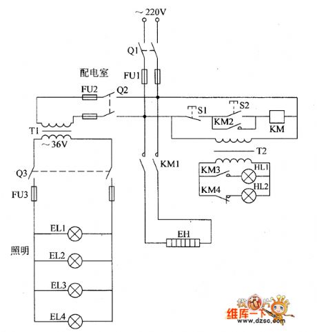
The greenhouse ground hotline controller circuit is composed of the power supply control circuit, working status indicator circuit and low voltage lighting circuit, and the circuit is shown as the chart. Control circuit is composed of the knife switch Q1, fuse FU1, control buttons S1, S2, AC contactor KM and ground hotline EH. Working status indicator circuit consists of the power transformer T1, lights HL1, H12, and the control contacts KM3, KM4 of KM. Low-voltage lighting circuit is composed of the power transformer T1, knife switches Q2, 03, fuses FU2, FU3 and lighting lamps EL1 ~ EL4. KM chooses CDC10-5 220V AC contactor. Q1 chooses HK2-30 Q1 knife switch; Q7 and Q3 use HK1-15 knife switches.
(View)
View full Circuit Diagram | Comments | Reading(1220)
Various IF filters circuit
Published:2011/6/17 9:45:00 Author:John | Keyword: IF filter
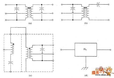
Most of the gain and selectivity of superheterodyne radio receivers are provided by the intermediate frequency (IF) amplifier. Therefore, it is a amplifier with high-gain and narrow bandwidth. IF power gain is typically between 60 dB and 120dB. Scuh range depends on the specific design for the receiver. Usually it has a much narrower bandwidth than the RF amplifier. For example, SSB receiver’s bandwidth is 2.8kHz and the CW receiver’s bandwidth is 500Hz. IF amplifier's role is to provide gain and selectivity for the receiver. The selective parts are achieved by a variety of filters.
(View)
View full Circuit Diagram | Comments | Reading(592)
Universal Active Filter circuit
Published:2011/6/15 10:40:00 Author:John | Keyword: Universal Active Filter
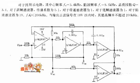
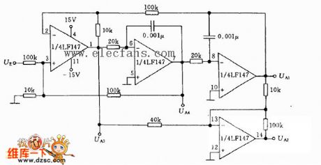
Universal Active Filter circuit is shown below.
Referring to the circuit as shown, its center frequency f0 = 3.4kHz, notch frequency fc = 9.5kHz and quality factor Q = 3.4. Transfer coefficient is 0.1for the high-frequency filter and is 1 for the band pass filter or the low-frequency filter. And 10.f0Q ≤ 200kHz is for the notch filter. When the output sinusoidal signal is with 10V, its highest frequency is not more than 200kHz.
(View)
View full Circuit Diagram | Comments | Reading(1246)
Brood thermostat circuit diagram
Published:2011/6/9 4:49:00 Author:Lucas | Keyword: Brood thermostat
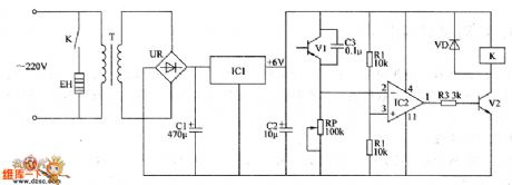
The brood temperature control circuit is composed of the power circuit and temperature detection control circuit, and the circuit is shown as the chart. Power circuit is composed of the power transformer T, bridge rectifier UR, filter capacitors C1, C2, and three-terminal voltage regulator integrated circuit IC1. Temperature detection control circuit is composed of the transistors V1, V2, resistors R1 ~ R3, potentiometer RP, capacitor C3, diode VD, operational amplifier integrated circuit IC2, heater EH and relay Κ. AC 220V voltage bucked by T , rectified by UR, filtered by C1, stabilized by IC1 can provide +6 V power supply for the temperature detection control circuit. R1 ~ R3 select 1/4W carbon film or metal film resistors. C1 and C2 select aluminium electrolytic capacitors with the voltage in 16V.
(View)
View full Circuit Diagram | Comments | Reading(1239)
active filter circuit
Published:2011/6/3 19:56:00 Author:chopper | Keyword: active filter
Its core frequency fo=3.4kHz,notch frequency fc=9.5kHz,quality factor Q=3.4.AS for high frequency filter,coefficient of transmission is 0.1;as for band-pass filter,the coefficient is 1;as for low frequency filter,the coefficient is 1;as for low amplitude filter,the coefficient is 1; as for notch filter,the the coefficient is 10.foQ≤200KHz.When output string signal is within 10V,its highest frequency is not more than 200KHz.
(View)
View full Circuit Diagram | Comments | Reading(676)
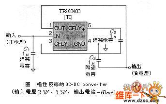
DC-DC with polarity inversion circuit
Published:2011/6/6 9:58:00 Author:chopper | Keyword: DC-DC, polarity inversion
View full Circuit Diagram | Comments | Reading(696)
electronic filter circuit
Published:2011/6/8 6:48:00 Author:chopper | Keyword: electronic filter
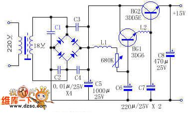
BG1 and BG2 form mulriple pipe.This circuit adds the filter element to the base of mulriple pipe which is different from others. The magnification coefficient of mulriple pipe β=β1•β2,so the filtering effect obtained from BG2 emitter is β1 times over L1 and C6,which equals that the big capacitance and inductance are added to the circuit.The most of hum in the circuit is restrained.And because the circuit adds L2 and C7 as well,their filtering effect was expanded β2 times by BG2,and leaches residual hum further.
(View)
View full Circuit Diagram | Comments | Reading(709)
Bandpass filter circuit
Published:2011/6/6 10:16:00 Author:chopper | Keyword: Bandpass filter
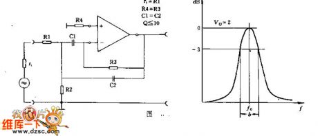
This circuit should determine the value of the R1 aforehand which is similar to the signal source resistance r1/ The principle of parameter selection is R4 = R3,C1 equals to C2 approximately,and Q equals to or lesser than R1,500K>R>1K,0.5uF>C>200pF.
(View)
View full Circuit Diagram | Comments | Reading(635)
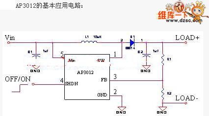
AP3012 positive-negative power supply circuit
Published:2011/6/6 9:54:00 Author:chopper | Keyword: positive-negative power supply
View full Circuit Diagram | Comments | Reading(1203)
digital isolation circuit
Published:2011/5/30 5:08:00 Author:chopper | Keyword: digital isolation
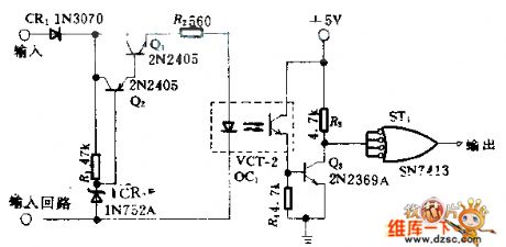
This circuit uses photocoupler to reach a absolute isolation between two digital circuit.The input signal even if it is low to 4V can also change the state of output,and the circuit will not be punctured even though a input peak around +100V.Q1,Q2 form current stabilizer and limit the loop current of the input end through the optoelectronic isolator in 7mA. Zener diode CR2 offers reference voltage and controls the current through R2.Schmitt trigger on the output end eliminates oscillation. (View)
View full Circuit Diagram | Comments | Reading(788)
Temperature Control Circuit Composed Of T-121 Temperatrue Sensor
Published:2011/5/22 0:48:00 Author:Robert | Keyword: Temperature, Control, Sensor
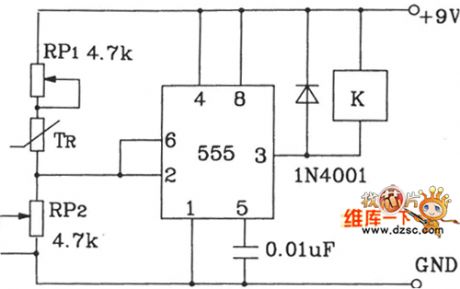
The controlled temperaturepoint can be set by adjusting RP1 and RP2. The 555 time-base circuit makes up the schmitt out-phase circuit. It uses the relays to achieve the equipment's automatical control. The T-121 temperature sensor makes the temperature control circuit which is shown below.
(View)
View full Circuit Diagram | Comments | Reading(928)
Standard Computer Interface Data Bus Circuit Composed Of LM35DZ Celsius Temperature Sensor And A/D Converter
Published:2011/5/22 3:56:00 Author:Robert | Keyword: Standard, Computer, Interface, Data Bus, Celsius, Temperature Sensor, A/D Converter
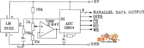
The Standard Computer Interface Data Bus Circuit Composed Of LM35DZ Celsius Temperature Sensor And A/D Converter is shown in the picture below.
(View)
View full Circuit Diagram | Comments | Reading(1207)
Small Electric Heater Temperature Control Circuit Composed Of Three-Wire Serial Interface Smart Temperature Sensor DS1620
Published:2011/5/18 7:08:00 Author:Robert | Keyword: Electric Heater, Temperature Control, Three-Wire, Serial, Interface, Smart, Temperature Sensor
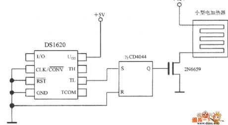
The Small Electric Heater Temperature Control Circuit Composed Of Three-Wire Serial Interface Smart Temperature Sensor DS1620 is shown in the picture below. When t<tL, TL would output high voltage level, which would set the 1/2CD4044 type RS trigger to be 1 and Q=1. This wouldmake the TMOS FET 2N6659 connected and also make the small electric heater's power connected. The 2N6659's UDSO=35V and PD=6.25W.
(View)
View full Circuit Diagram | Comments | Reading(2760)
Two-Wire Serial Interface Smart Temperature Sensor TCN75 And 89C51 MCU Interface Circuit
Published:2011/5/18 6:49:00 Author:Robert | Keyword: Two-Wire, Serial, Interface, Smart, Temperature Sensor, MCU
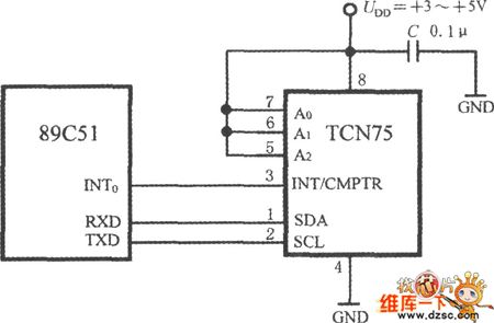
The interface circuit of TCN75 and 89C51 is shown in the picture below. Byletting the TCN75's address input ports A2~A0 all connect to high voltage level UDD, the address code is changed to be 111. The 89C51 can achieve the chip-selection function by software. The 89C51's series data receiving port (RXD) and series data transmitting port (TXD) are connected to the TCN75's SDA port and SCL port separately. TCN75's interrupt/compare signal is connected to 89C51's interrupt port INT0.
(View)
View full Circuit Diagram | Comments | Reading(1148)
Water Temperature Automatically Control Device Circuit
Published:2011/5/17 7:22:00 Author:Robert | Keyword: Water Temperature, Automatically Control Device
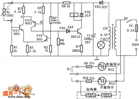
The Water Temperature Automatically Control Device Circuit is shown below.
(View)
View full Circuit Diagram | Comments | Reading(1288)
Temperature Control Circuit With Upper And Lower Limits
Published:2011/5/16 9:59:00 Author:Robert | Keyword: Upper And Lower Limits, Temperature, Control
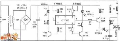
The Temperature Control Circuit With Upper And Lower Limits is shown below.
(View)
View full Circuit Diagram | Comments | Reading(850)
| Pages:5/6 123456 |
Circuit Categories
power supply circuit
Amplifier Circuit
Basic Circuit
LED and Light Circuit
Sensor Circuit
Signal Processing
Electrical Equipment Circuit
Control Circuit
Remote Control Circuit
A/D-D/A Converter Circuit
Audio Circuit
Measuring and Test Circuit
Communication Circuit
Computer-Related Circuit
555 Circuit
Automotive Circuit
Repairing Circuit