
Temperature Control
Index 2
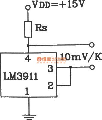
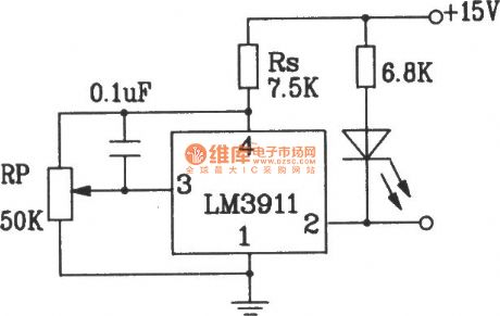
Single power supply temperature measurement circuit composed of LM3911 monolithic temperature control IC
Published:2011/8/22 3:29:00 Author:Jessie | Keyword: Single power supply, temperature measurement circuit, monolithic temperature control IC
View full Circuit Diagram | Comments | Reading(1088)
Aquarium automatic temperature constant circuit
Published:2011/8/26 3:07:00 Author:Jessie | Keyword: aquarium, temperature constant
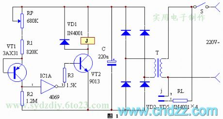
When the temperature of water below the set temperature (tropical fish is usually 23-27℃), 3AX31's Iceo is lower, its resistance increases,a isthe low level, it will output high potential after IC1A reversed-phase, VT2 connected, relay j1 suck close, hot converter R4 works. Conversely, a is the high level, VT2 stops, j1 releases, R4 blackouts.
Thermal componentsshould choosegermanium transistors 3AX31, 3AX34 with better temperature curve.The inverter chooses CD4049 or CD4069. Power transformeruses 10V ,2-5W small transformers.
The tank thermostat is suitable for tropical fish breeding feeding enthusiasts, andthe circuit issimple and effective.
(View)
View full Circuit Diagram | Comments | Reading(1523)
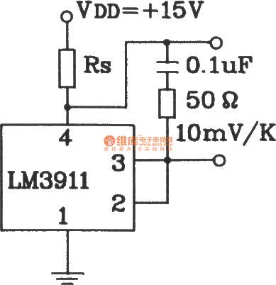
Capacitive load temperature measurement circuit composed of LM3911 monolithic temperature control integrated circuit
Published:2011/8/26 2:48:00 Author:Jessie | Keyword: Capacitive load, temperature measurement, monolithic temperature control
View full Circuit Diagram | Comments | Reading(805)
Temperature overheat detection alarm circuit composed of LM3911 monolithic temperature control integrated circuit
Published:2011/8/19 2:57:00 Author:Jessie | Keyword: Temperature overheat detection alarm, monolithic temperature control

View full Circuit Diagram | Comments | Reading(1120)
Plus benchmark power supply temperature detection circuit composed of LM3911
Published:2011/8/19 2:51:00 Author:Jessie | Keyword: Plus benchmark power supply, temperature detection, monolithic temperature control
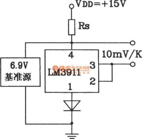
Plus benchmark power supply temperature detection circuit composed of LM3911 monolithic temperature control integrated circuit (View)
View full Circuit Diagram | Comments | Reading(807)
Two-supply temperature measurement circuit composed of LM3911 monolithic temperature control integrated circuit
Published:2011/8/19 2:57:00 Author:Jessie | Keyword: Two-supply temperature measurement, monolithic temperature control
View full Circuit Diagram | Comments | Reading(1364)
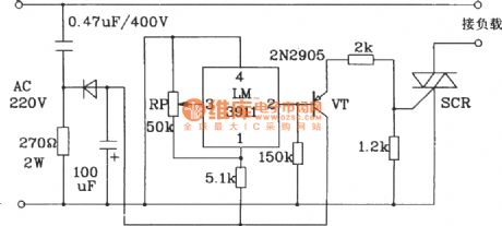
Start refrigeration equipment temperature control circuit composed of LM3911 monolithic temperature control IC
Published:2011/8/22 3:30:00 Author:Jessie | Keyword: Start refrigeration equipment , temperature control circuit, monolithic temperature control IC
View full Circuit Diagram | Comments | Reading(1083)
On-off temperature control circuit with Integrated flip-flop 5B
Published:2011/8/26 1:59:00 Author:Jessie | Keyword: temperature control circuit, integrated flip-flop

These three circuits are supplied by AC 220V voltage, and the given temperature range is 5 ℃ ~ 30 ℃, and it uses integrated trigger TDA1024 and Triacs BT139,and the heating power is 2KW.
Room temperature (actual temperature) is measured by the thermistor, which is connected in a branch circuit of the bridge. The potentiometer R can adjust the given stable value. If the actual voltage value of pin 5 exceeds the given threshold voltage of pin 4, then the thyristor gate has no trigger pulse. On the contrary, there is trigger pulse, and the heating resistor RL gets power. In order to make the comparator has the minimum hysteresis, pin 3 is hung up, and the temperature difference is about 0.3K.
(View)
View full Circuit Diagram | Comments | Reading(2185)
Dibit temperature regulation circuit with complementary transistor
Published:2011/8/26 1:44:00 Author:Jessie | Keyword: Dibit temperature regulation , complementary transistors
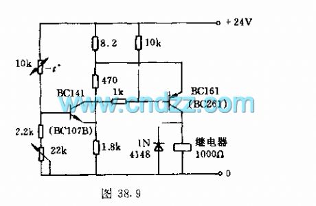
Thegiven temperature and the actual temperature are compared in the bridge road circuit which is composedof theresistor and thermistor. The relationship between input transistor threshold voltage and temperature is negligible, because the threshold voltage of this circuit is only about 5% of the given effective voltage.
The temperature increases while the value of resistor declines, the voltage between NPN transistor base increases, the collector current controls the base of PNP transistor by 1kΩ current limiting resistor, relay suck closes. The hysteresis loop of the circuit is about 0.5%.
(View)
View full Circuit Diagram | Comments | Reading(1342)
Temperature measurement circuit with silicon heating sensitive elements
Published:2011/8/26 2:48:00 Author:Jessie | Keyword: Temperature measurement, silicon heating sensitive elements
This circuit makes silicon heating sensitive elements as sensor,and it isconnected to the brige road and about 2.5V constant voltage. Operational amplifier V1is used as pulse converter, V2 is used as amplifier. Output voltage is between 0 ~ 5V, and it has 50mV/K scale factor between the range of 0 to 100 ℃. The temperature range endpoint is connected an adjusting circuit. First, adjusting the R9 at 0 ℃, then adjusting R4 at 100 ℃. Measurement error can be restricted in ± 0.2K.
(View)
View full Circuit Diagram | Comments | Reading(707)
Temperature control circuit with SL590
Published:2011/8/26 2:41:00 Author:Jessie | Keyword: temperature control
As shown in figure, it iscomposedof temperature sensor, trigger circuit, relay control circuit, language circuit, audio power amplifier circuit andAC step-down rectifier circuit, etc. Temperature control circuituses SL590,and it copies American AD company's AD590,which is the current type 2-end device.
(View)
View full Circuit Diagram | Comments | Reading(636)
Cold shutoff temperature control circuit with TWH9205
Published:2011/8/26 2:14:00 Author:Jessie | Keyword: cold shutoff, temperature control
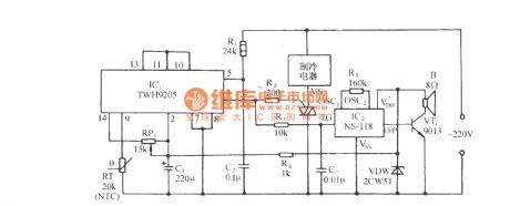
As shown in figure, this circuit is composedofthe zero switch control circuit composedof TW9205 andits peripheral components, SCR drive refrigeration control circuit and sound circuit. The temperature sensor RT in graph uses negative temperature coefficient (NTC) thermal resistor, which is connected to the differential switch amplifier reversed-phase input terminal(pin 9) of TWH9205; Differential switch amplifier phase input terminal(pin 13) and potential clamp fixed end pin 10, 11. Adjust RP1's value so that TWH9205 in set temperature range outputs a low level, and SCR VS in a globe state. When thermistors RT increases to a predetermined value with the temperature, output state of differential switch amplifier is inside the TWH9205, an output terminal of the TWH9205 sents to the high level whenAC powerbecomes zero, SCR VS connected, appliancesget electricity and work.
(View)
View full Circuit Diagram | Comments | Reading(1211)
The circuit diagram of high Q notch filter
Published:2011/8/9 3:28:00 Author:Felicity | Keyword: high Q notch filter
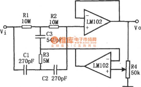
This figure shows the circuit of high Q notch filter. The operational amplifier in the low figure comprise voltage follower. The potentiometer R4 can change the value of Q (from 0.3 to 50). And the notch frequency : f0=1/2πR1C1. To avoid the drifting of f0, silvering mica or carbonate capacitor and matallic film resistance are needed. To reach 60dB attenuation, the allowance of resistance is below 0.1% ,and the allowance of capacity is below. To make LM102 work steadily, a 0.01μF capacitor is needed to filter the power. (View)
View full Circuit Diagram | Comments | Reading(1688)
Brood thermostat
Published:2011/8/10 3:48:00 Author:Ecco | Keyword: Brood thermostat
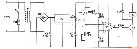
The brood thermostat circuit is composed of the power supply circuit and temperature detection control circuit, and it is shown in Figure 4-41. Power supply circuit is composed of the power transformer T, bridge rectifier UR, filter capacitors Cl, C2, and three-terminal voltage regulator integrated circuit ICl. Temperature detection control circuit consists of transistors Vl, V2, resistors Rl-R3, potentiometer RP, capacitor C3, diode VD, operational amplifier integrated circuit IC2, heater EH and relay K. Rl-R3 use 1/4W metal film resistors or carbon film resistors. C3 uses the monolithic capacitor or polyester capacitor.
(View)
View full Circuit Diagram | Comments | Reading(1409)
Fish farming thermostat controller 2
Published:2011/8/8 21:52:00 Author:Ecco | Keyword: Fish farming, thermostat controller
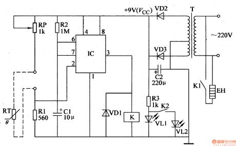
The fish farming thermostat controller circuit is composed of the power supply circuit and temperature detection control circuit, and it is shown in Figure 4-23. Power supply circuit is composed of the power transformer T, rectifier diodes VD2, VD3, filter capacitor C2, limiting resistor R3 and power indicator LED VLl. Temperature detection control circuit consists of the thermistor RT, resistors Rl, R2, capacitor Cl, potentiometer RP, time-base integrated circuit IC, heating working indicating light-emitting diode Vm, relay K and diode VDl. Rl-R3 use 1/4W metal film resistors or carbon film resistors.
(View)
View full Circuit Diagram | Comments | Reading(2088)
Fish farming thermostat controller 1
Published:2011/8/8 21:48:00 Author:Ecco | Keyword: Fish farming , thermostat controller
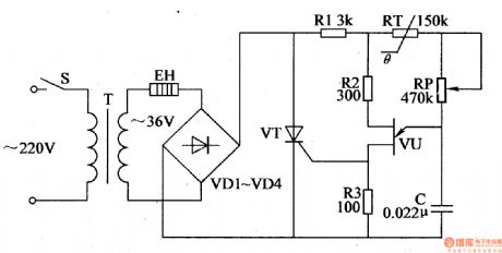
The fish farming thermostat controller circuit is composed of the power supply circuit and temperature control circuit, and it is shown in Figure 4-22. Power supply circuit consists of the power switch S, power transformer T, electric heater EH and rectifier diodes VDI-VD4. Temperature control circuit consists of the resistors Rl-R3, thermistor RT, potentiometer RP, capacitor C, single-junction transistor VU and thyristor VT. Rl select the 1/2W metal film resistor; R2 and R3 select the 1/4W metal film resistors or carbon film resistors. RP chooses the solid synthetic membrane potential potentiometer. C uses the monolithic capacitor or polyester capacitor.
(View)
View full Circuit Diagram | Comments | Reading(950)
AC-DC three-digit voltmeter circuit
Published:2011/8/11 4:36:00 Author:John | Keyword: three-digit voltmeter
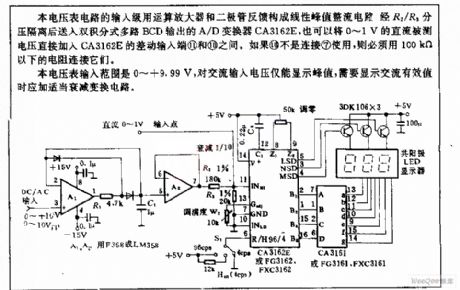
The voltmeter circuit’s input stage uses operational and a diode feedback to form a linear peak rectifier circuit. Then the circuit is isolated via R2/R3 divider and is sent to A / D converter CA3162E output from the dual integral multiple BCD. It can be also said to that the 0 ~ 1V DC test voltage is directly added between the differential inputs ⑾ and ⑽ of the CA3162E. If ⑽ is not connected to ⑺ for use, resistor with less than100kΩ should be used to connect to them. The voltmeter input ranges from 0 to +9.99 V. It only displays the peak value of the AC input voltage. When AC rms should be displayed, the transform circuit is needed to attenuate appropriately.
(View)
View full Circuit Diagram | Comments | Reading(2158)
LCD direct drive circuit
Published:2011/8/11 3:31:00 Author:John | Keyword: LCD, direct drive
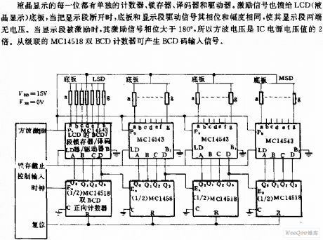
Every phase of LCD has the separate counter, latch, decoder and driver. Excitation signal is also fed back to the floor plate of LCD (liquid crystal display). When the display segment is disconnected, the floor plate and display segment drive signal to be with the same phase and amplitude. So there is no voltage across the segment. When the segment is encouraged, the excitation signal phase is greater than 180 °. So the square-wave voltage is two times more than the IC supply voltage. Dual-counter BCD from the cascade MC14518 can input signals by generating BCD code.
(View)
View full Circuit Diagram | Comments | Reading(1220)
Using temperature and frequency converter high-precision temperature control circuit diagram
Published:2011/8/9 2:28:00 Author:Rebekka | Keyword: high-precision temperature control
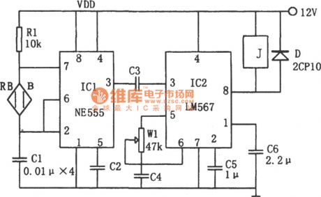
Because the RB changes with temperature, the fc also changes with temperature. Audio decoder phase lock loop uses a single audio decoder integrated circuit IC2 (LM567), the center frequency is xsl-fo = 1/1.1 Rw1C4. The adjustment of W1can setxsl-fotemperature frequency. When the IC1 oscillation frequency is the same with the center of the IC2, fc frequency xsl-fo is consistent. The LM567 outputs low level (8) foot) and makes relay J suck close. It will open the load. (View)
View full Circuit Diagram | Comments | Reading(1983)
Single-phase thyristor zero trigger electric stove temperature control circuit diagram
Published:2011/8/11 2:09:00 Author:Rebekka | Keyword: Single-phase thyristor, electric stove , zero trigger ,
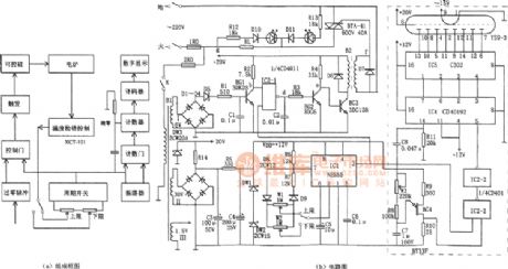
The figure shows the single-phase thyristor zero trigger electric furnace temperature control circuit. This temperature device is composed of the signal detection temperature control circuit, the zero detection circuit, cycle switch, trigger control and digital display etc. Itis used withXCT-101 temperature control meter together. It can monitor the 6 ~ 8 kW single-phase thyristor zero trigger electric furnace temperature. The temperature and thermal insulation are ajustable in 1% ~ 99%. The winding I1 of transformer B1, D1 ~ D4, D6, C1, BG1 and other components form the zero pulse detection circuit, IC2-l (1 / 4 CD4011) is the controlling door, and in the effect of the pulse output by cycle switch (IC1), it outputs a group of zero-crossing detection pulse, which is inverting amplified by BG2 and output by isolated transformer BG3. (View)
View full Circuit Diagram | Comments | Reading(3201)
| Pages:2/6 123456 |
Circuit Categories
power supply circuit
Amplifier Circuit
Basic Circuit
LED and Light Circuit
Sensor Circuit
Signal Processing
Electrical Equipment Circuit
Control Circuit
Remote Control Circuit
A/D-D/A Converter Circuit
Audio Circuit
Measuring and Test Circuit
Communication Circuit
Computer-Related Circuit
555 Circuit
Automotive Circuit
Repairing Circuit