Time Control
Voltage Regulator (the 4th)
Published:2011/7/3 5:06:00 Author:Felicity | Keyword: Voltage Regulator (the 4th) | From:SeekIC
Work of the circuit
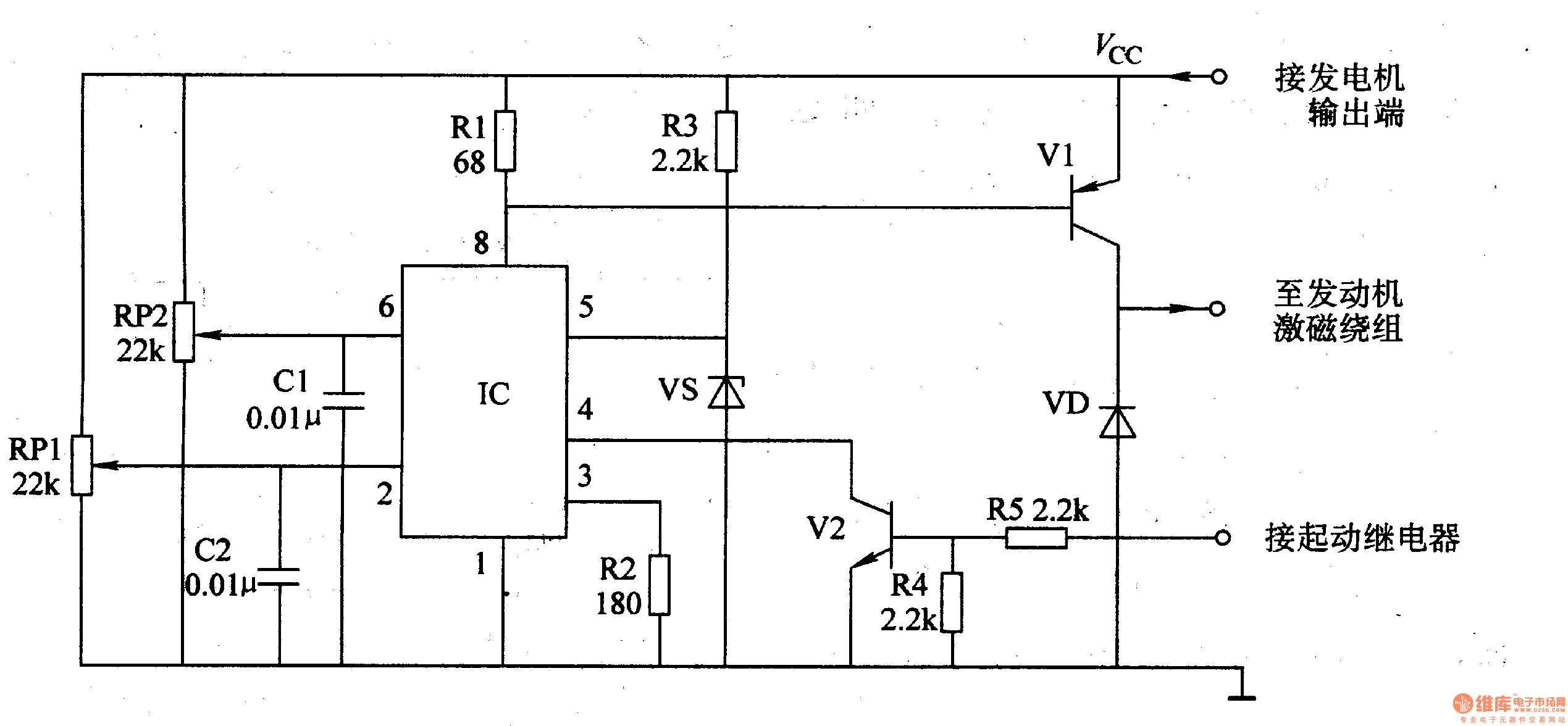
The circuit consists of time-based integrated circuit IC, potentiometer RP1, Rm, capacitor C1, C2, resistor R1-R5, stabilizing diode VS, diode VD and transistor V1 and V2. (It is showed in picture 7-144.)
Turn on the power switch of the mobile and the motor is starting. Here V2 is transmitted. When the motor works, V2 is cut-off. The exporting voltage of the AC motor is adjusted by R3 and VS. Then it supplies 6V reference voltage to pin5 of IC. When the exporting voltage is less than 14.4 V, the exporting voltage on the motor is increasing. When the exporting voltage reaches 14.9V, the exporting voltage is decreasing. The process repeats to keep the exporting voltage in the range of 14.4-14.9V.
RP1 is used to set the least voltage.
RP2 is used to set the highest voltage.
Reprinted Url Of This Article:
http://www.seekic.com/circuit_diagram/Control_Circuit/Time_Control/Voltage_Regulator_the_4th.html
Print this Page | Comments | Reading(3)

Article Categories
power supply circuit
Amplifier Circuit
Basic Circuit
LED and Light Circuit
Sensor Circuit
Signal Processing
Electrical Equipment Circuit
Control Circuit
Remote Control Circuit
A/D-D/A Converter Circuit
Audio Circuit
Measuring and Test Circuit
Communication Circuit
Computer-Related Circuit
555 Circuit
Automotive Circuit
Repairing Circuit
Code: