
Battery Backup and Switchover Circuit
Index
Regulator DC-DC Circuit and Pin of Power Supply Monitor and NJM3254 Switched Regulator-controlled Circuit
Published:2011/9/13 1:50:00 Author:Zoey | Keyword: Regulator, DC-DC Circuit, Pin of Power Supply Monitor, Switched Regulator Circuit
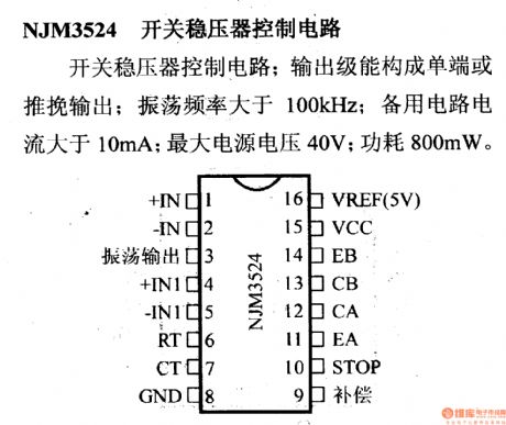
The output terminal of NJM3254 switched regulator-controlled circuit can constitute single terminal or push-pull output. Its oscillation frequency exceed 100kHz. Current of the spare circuit is larger than 10mA. Maximum voltage of the power supply is 40V, and the power is 800mW. (View)
View full Circuit Diagram | Comments | Reading(958)
Regulator DC-DC Circuit and Pin of Power Supply Monitor and its Main Features-MAX662
Published:2011/9/13 2:36:00 Author:Zoey | Keyword: Regulator, DC-DC Circuit, Flash Reservoir, Programmable Power Supply
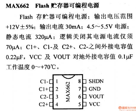
MAX662 refers to Flash reservoir programmable power supply. For MAX 662, the output voltage range is +12V ±5%, output current is 30mA, power is 4.5~5.5V and static current is 320µA. When logically closed, the current of power supply can be limited to 70µA. External capacitance between C1+, C1-, C2+ and C2- is 0.22µF, while between VCC and VOUT connected to the ground is 0.1µF. The working temperature range is 0~+70℃. (View)
View full Circuit Diagram | Comments | Reading(760)
Regulator DC-DC Circuit and Pin of Power Supply Monitor and Reverse DC-DC Converter
Published:2011/9/13 2:22:00 Author:Zoey | Keyword: Regulator, DC-DC Circuit, Pin of Power Supply Monitor, RP
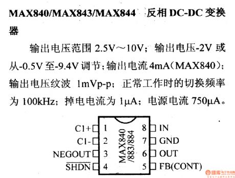
Voltage output of MAX840/MAX843/MAX844 RP DC-DC converters ranges from 2.5V to 10V. The output voltage can be adjusted to -2V or -0.5V~-9.4V. Output current of MAX840 is 4mA and output voltage wave is 1mVp-p. In normal operation, the switching frequency is 100kHz, the power-off current is 1µA and current of power supply is 750µA. (View)
View full Circuit Diagram | Comments | Reading(1007)
Flyback Synchronous Rectifier Control Circuit of Adapter
Published:2011/7/13 7:51:00 Author:Michel | Keyword: Synchronous, Rectifier Control Circuit
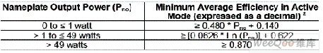
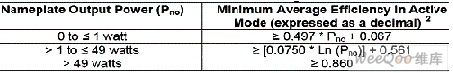
With the development of consumer electronics, energy consumption rate in global electricity of its external power supply(adopter) is dramatically increasing which has been seen as a great energy consumption user.Take America as example, adapters consumes 300 billion degrees electricity per year and it is 11% of the entire country electricity.Today energy conservation and emission reduction is pervasive,at present all governments' regulations are more and more strict to exteral power supply.The United States energy star makes more strict regulations to the average efficiency for external power supply.
Figure 1 shows the power efficency when the output voltage is lagrger than 6V. (View)
View full Circuit Diagram | Comments | Reading(566)
Step Voltage Generating Circuit of Output Fifth Voltage
Published:2011/6/14 13:18:00 Author:Michel | Keyword: Fifth Voltage, Step Voltage, Generating Circuit
Circuit's Functions
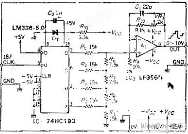
Ladder is a waveform that voltage shows ladder shape change with the time increases.In other words,it's a kind of bad slope linear waveform caused by digital circuit.In this circuit,at most 15 steps voltage can be output.The average time of per level is determined by external input clock and level differences of output voltage are equal.This cuircuit can be used if you want to gradually improve the response of the voltage.
Circuit's Work Principle
C1 is four binary counter and it constitutes 4 D - A converter when R - 2R trapezoidal resistor network are added to its output terminal.
(View)
View full Circuit Diagram | Comments | Reading(696)
Three LED Circuit Driven by MAX1574 Charge-Pump
Published:2011/6/19 7:24:00 Author:Michel | Keyword: Charge-Pump, Three LED Circuit
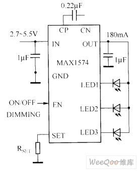
The white LED circuit driven by MAX1574 charge-pump is showed as above.This circuit uses 180mA current to drive three whiteLED.
1 MHz switching frequencies allows the charge pump touse small size ceramic capacitors.
Picture:Three LED Circuit Driven by MAX1574 Charge-Pump (View)
View full Circuit Diagram | Comments | Reading(674)
Serial Adjustment Stabilized Voltage Supply Circuit
Published:2011/6/4 22:28:00 Author:Michel | Keyword: Serial Adjustment, Stabilized Voltage, Supply Circuit

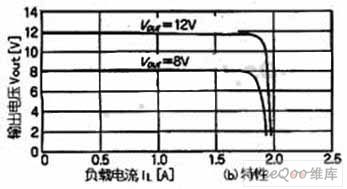
The right picture is adjustable stabilized voltage power which uses crystal triode to output voltage.This circuit adjusts the output voltage by changing high-power crystal triode, tr1's voltage of load series. The output voltage,Vout,depends on A'svoltage,namely,Vref+VBE2.In the right formula,Vref(5.1V)is the voltage of voltage regulator diode,VBE2 is the emitter-to-base voltage of crystal triode Tr2,VR1 is variable resistor.Variable range of VR1 is 0~5kΩ so the variable range of output voltage is 7.6~12.8V.When VR1 sliding parts contact undesirable, the output voltage will be a minimum voltage. (View)
View full Circuit Diagram | Comments | Reading(628)
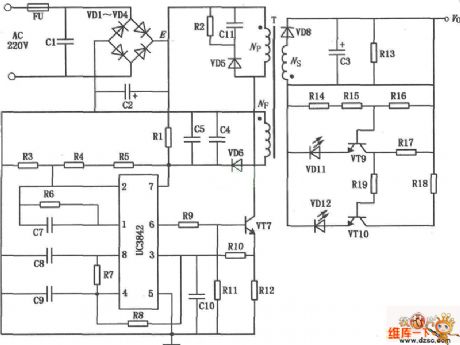
electric bicycle battery charger UC3842 circuit diagram
Published:2011/5/4 9:34:00 Author:Nancy | Keyword: electric bicycle, battery charger
View full Circuit Diagram | Comments | Reading(5514)
Self-Locking Sound Control Switch Circuit
Published:2011/4/23 9:00:00 Author:Robert | Keyword: Self-Locking, Sound Control, Switch
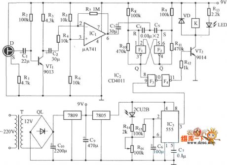
Self-Locking Sound Control Switch Circuit is shown below:
(View)
View full Circuit Diagram | Comments | Reading(1017)
Anti-Interference Power Saving Switch Circuit
Published:2011/4/23 9:16:00 Author:Robert | Keyword: Anti-Interference, Power Saving Switch
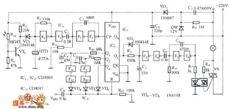
Anti-Interference Power Saving Switch Circuit is shown below:
(View)
View full Circuit Diagram | Comments | Reading(706)
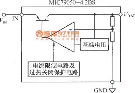
MIC79050-4.2BS internal structure schematic diagram
Published:2011/3/21 2:05:00 Author:Joan | Keyword: internal structure schematic
View full Circuit Diagram | Comments | Reading(763)
Circuit Categories
power supply circuit
Amplifier Circuit
Basic Circuit
LED and Light Circuit
Sensor Circuit
Signal Processing
Electrical Equipment Circuit
Control Circuit
Remote Control Circuit
A/D-D/A Converter Circuit
Audio Circuit
Measuring and Test Circuit
Communication Circuit
Computer-Related Circuit
555 Circuit
Automotive Circuit
Repairing Circuit