
Power-Supply Circuits-AC to DC
Index
ISOLATED AC CURRENT MONITOR
Published:2012/9/4 3:31:00 Author:jailer
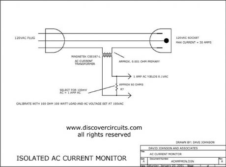
This circuit uses a small AC current transformer from Magnetek to produce an isolated voltage proportional to the AC current in the primary winding. The transformer contains a single turn primary with a low 0.001-ohm resistance. It can easily handle 30 amps of AC current and provides at least 500vac of isolation. With the components shown, the output AC voltage is scaled so 1 amp of current produces 100mv of AC voltage. (View)
View full Circuit Diagram | Comments | Reading(2)
Bus-Storage Integrated Circuit
Published:2011/9/14 0:12:00 Author:Zoey | Keyword: Bus Storage, Integrated Circuit
ST7C08 is usually used to support to the use of CPU (M37221M6) for achieving control functions of digital TVs .
1 Features
ST7C08 mainly consist of data recovery IC, parallel/ serial conversion, electrically erasable, programmable read-only memory, a high voltage (5V) pump / timing, start / stop logic, serial logic control, X / Y decode, address comparison, the data byte address / count and data output / recognition logic and other components. The inner circuit diagram and typical application circuit of the integrated block have been shown in Figure 1.
2 pin functions and data
ST7C08 and its pin functions of the integrated circuit and relevant data have been listed in Table 1.
(View)
View full Circuit Diagram | Comments | Reading(737)
Automatic switching circuit of Multimeter AC to DC
Published:2011/7/17 23:12:00 Author:Sophia | Keyword: Automatic switching, Multimeter AC to DC
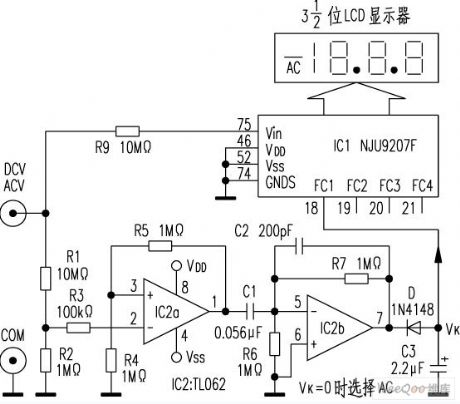
The AC and DC measurement conversion of ordinary digital multimeter is completed by manual operation. New digital multimeter DT860D adopts Automatic range switching chip NJU9207F, and is equiped with external auxiliary circuit to achieve AC - DC (AC / DC) automatic conversion measurements.
AC / DC automatic conversion circuit is shown below.
(View)
View full Circuit Diagram | Comments | Reading(2730)
AC Voltage Regulator Fourteen
Published:2011/6/3 8:13:00 Author:Michel | Keyword: AC, Voltage Regulator, Fourteen
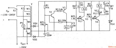
The AC voltage regulator introduced in the example has the functions automatical voltage regulation and overvoltage protection.Its input voltage range is 150-240V,output voltage is 220V±l0V and output power is 500W.
Circuit's Wrok Principle
The rgulator circuit is composed of voltage test control circuit,boosting or dropping voltage circuit and overvoltage protection circuit and it is showed as the picture 5-53. The voltage test control circuit consists of transformer T,communication diode VD1,VD2,capacitor C1-C3,transistor V1-V3,resistor,R1-R4,potentiometer RP1,RP2 and LED VL1 and relay K1. (View)
View full Circuit Diagram | Comments | Reading(5291)
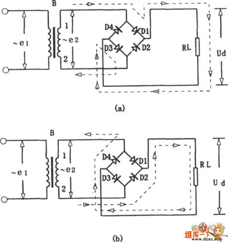
Single-Phase Bridge Rectifier Circuit
Published:2011/5/17 7:26:00 Author:Robert | Keyword: Single-Phase, Bridge, Rectifier
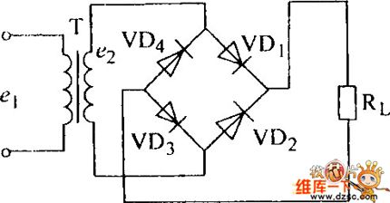
The Single-Phase Bridge Rectifier Circuit is shown below.
(View)
View full Circuit Diagram | Comments | Reading(1709)
Bridge Rectifier Circuit
Published:2011/5/17 6:57:00 Author:Robert | Keyword: Bridge, Rectifier
The Bridge Rectifier Circuit is shown below.
(View)
View full Circuit Diagram | Comments | Reading(1001)
A Three-Phase Bridge Rectifier π Type Filter Circuit
Published:2011/5/11 7:13:00 Author:Robert | Keyword: Three-Phase Bridge, Rectifier, π Type Filter
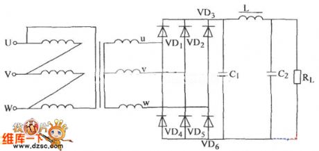
A Three-Phase Bridge Rectifier πType Filter Circuit is shown below.
(View)
View full Circuit Diagram | Comments | Reading(1320)
About Single-Phase Bridge Rectifier π Type Filter Circuit
Published:2011/5/11 7:11:00 Author:Robert | Keyword: Single-Phase Bridge, Rectifier, π Type Filter
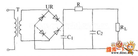
The About Single-Phase Bridge Rectifier π Type Filter Circuit is shown below.
(View)
View full Circuit Diagram | Comments | Reading(885)
Circuit Categories
power supply circuit
Amplifier Circuit
Basic Circuit
LED and Light Circuit
Sensor Circuit
Signal Processing
Electrical Equipment Circuit
Control Circuit
Remote Control Circuit
A/D-D/A Converter Circuit
Audio Circuit
Measuring and Test Circuit
Communication Circuit
Computer-Related Circuit
555 Circuit
Automotive Circuit
Repairing Circuit