
Power-Supply Circuits-Fixed
Index 2
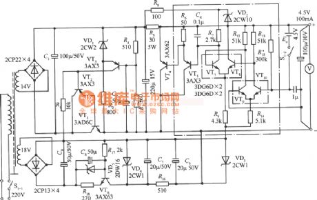
4.5V Precision power circuit diagram
Published:2011/8/9 2:18:00 Author:Rebekka | Keyword: 4.5V Precision power
View full Circuit Diagram | Comments | Reading(881)
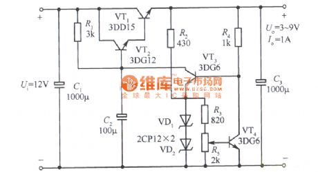
Adjustable regulated power supply circuit diagram with 3~9V sampling ratio
Published:2011/8/9 2:03:00 Author:Rebekka | Keyword: Adjustable, regulated power supply , 3~9V , sampling ratio
View full Circuit Diagram | Comments | Reading(1259)
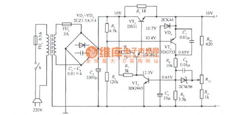
IOV fixed power supply circuit diagram with l20~250V grid voltage
Published:2011/8/9 2:01:00 Author:Rebekka | Keyword: Grid voltage , fixed power supply, l20~250V
View full Circuit Diagram | Comments | Reading(1404)
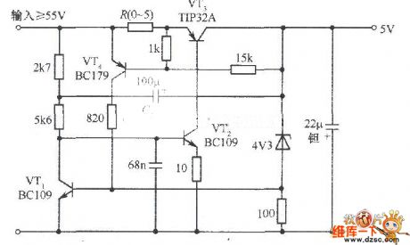
5V fixed voltage power supply circuit diagram with over cut-off protection
Published:2011/8/17 3:05:00 Author:Rebekka | Keyword: Over cut-off protection, fixed voltage power supply, 5V
View full Circuit Diagram | Comments | Reading(1228)
Regulated power supply circuit diagram composed of L296 monolithic high-current switching power supply chip
Published:2011/8/17 2:54:00 Author:Rebekka | Keyword: Regulated power supply , monolithic high-current , switching power supply chip
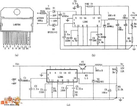
The features of L296 monolithic high-current switching power supply chip are: (1) Perfect protection function. It is equipped with soft start, over current, overheating, overvoltage protection; (2) The maximum output current is 4A, 160W power, output voltage is adjustable between 5.1 ~ 40V; (3) Special features: Workban control, synchronization control(in a few pieces long on output, to ensure the same frequency), reset circuit (power supply can provide state of the detection signal), crowbar overvoltage protection circuit(When the output voltage exceeds a preset 20% rated. It produces a 100mA of drive signals for triggering external protection circuit action). Figure (c) shows the current expansion of the circuit form. (View)
View full Circuit Diagram | Comments | Reading(4619)
TD4919 switch regulator power supply circuit diagram composed of switching power supply IC
Published:2011/8/17 2:38:00 Author:Rebekka | Keyword: switch regulator, power supply , switching power supply
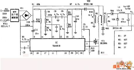
The AC input voltage of the circuit is 185~240V, DC output voltage is 10V, output current is 5A. The features are: It has the function of monitoring output voltage, overvoltage and undervoltage and the function of dynamic current limit.
Regulation process is: Output voltage Vo passes R15 and PR partial pressure trough R16 and R17 feedback to pin18 and pin 19 of TD4919. The internal control of TD4919 is used to adjust its output switch pulse duty cycle to reach a stable output voltage Vo. The monitor of power supply output current is realised by the sample voltage of R11 monitoring(R11 is the sample voltage of VT source current). It produces control signalto control the output switch pulse to achieve the limit of output current. Undervoltage and overvoltage monitoring is achieved by R4, R5, R6, pin12, pin13 and the internal control circuit of TD4919. (View)
View full Circuit Diagram | Comments | Reading(1576)
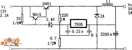
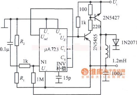
Switch regulator power supply circuit diagram made by three-terminal regulator
Published:2011/8/17 3:20:00 Author:Rebekka | Keyword: three-terminal regulator , switch regulator power supply
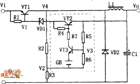
Equivalent circuit of switching regulator power supply:
Switch regulator power supply circuit diagram made by three-terminal regulator is shown as above. Itsworking principle can be read through the equivalent circuit diagram. The output voltage VO declines a little because of some reasons. The partial pressure V3 on R5 and R6 also declines. It is enlarged by VT3, then Ic3 minishes, Ic2 increases, the current passing R1 and VD1 increases, V1 declines. It makes Ic1 increase, V4 rise, V4 passing the partial voltage of R2 and R3, V2 increase and V3 decline. The process is a reaction of positive chain feedback. Finally VT1 and VT2 are conducted, VT3 stops, Ic1 charges to L1 and C1. It makes Vo increase gradually. (View)
View full Circuit Diagram | Comments | Reading(876)
Line current restrictor circuit diagram
Published:2011/8/2 2:24:00 Author:Rebekka | Keyword: Line current restrictor
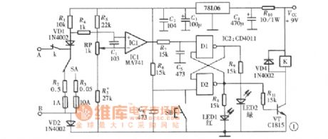
The figure shows the current of the line current restrictor limit circuit. Once the value of the current exceeds the limit value, the controller relay will cut off the power supply immediately. The current limit value is continuously adjustable from l00mA to 10A. The components of the circuit is shown as above. The whole circuit includs the line current sample and voltage comparator, RS flip-flop and control relay. It is composed of an operational amplifier MA741 and a four - two input NAND gate CD4011. (View)
View full Circuit Diagram | Comments | Reading(984)
Negative pressure switch regulated power supply circuit diagram
Published:2011/8/2 2:26:00 Author:Rebekka | Keyword: Negative pressure switch, Vacuum switch regulated power supply
View full Circuit Diagram | Comments | Reading(966)
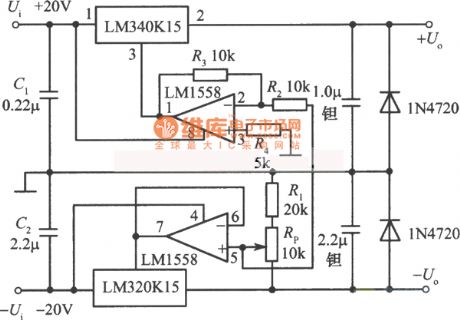
±5 to ±l8V adjustable tracking regulated power supply circuit diagram
Published:2011/5/10 2:30:00 Author:Rebekka | Keyword: regulated power supply
View full Circuit Diagram | Comments | Reading(745)
0 to 20V 1A adjustable regulated power supply circuit diagram
Published:2011/5/10 2:30:00 Author:Rebekka | Keyword: adjustable regulated power supply
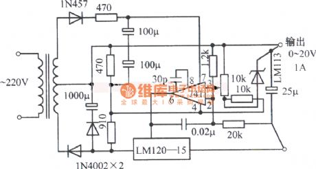
0 to 20V 1A adjustable regulated power supply circuit diagram composed of LM120-15 and zener diode LM741. (View)
View full Circuit Diagram | Comments | Reading(845)
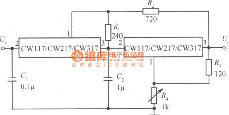
Tracking integrated power supply circuit composed of two CW117 CW217 CW317
Published:2011/8/3 2:40:00 Author:Rebekka | Keyword: Tracking integrated power supply
View full Circuit Diagram | Comments | Reading(566)
Universal regulated power supply circuit diagram
Published:2011/5/10 2:24:00 Author:Rebekka | Keyword: Universal regulated power supply

View full Circuit Diagram | Comments | Reading(687)
Positive and negative output voltage tracking regulated power supply integrated circuit diagram 1
Published:2011/5/10 2:23:00 Author:Rebekka | Keyword: output voltage tracking , regulated power supply
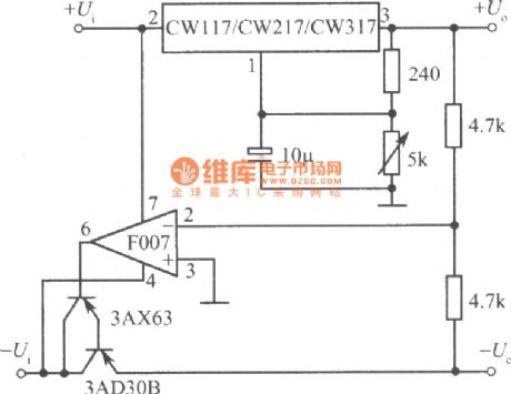
Here is the diagramof positive and negative output voltage tracking regulated power supply integrated circuit composed of CW117, CW217 and CW317. (View)
View full Circuit Diagram | Comments | Reading(873)
Positive and negative output voltage tracking regulated power supply integrated circuit diagram 2
Published:2011/5/10 1:36:00 Author:Rebekka | Keyword: Positive and negative output voltage tracking, regulated power supply
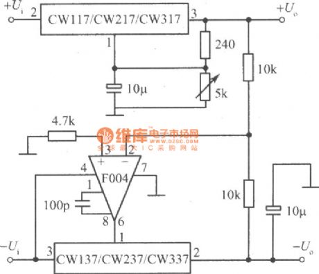
Here is the diagram 2of positive and negative output voltage tracking regulated power supply integrated circuit composed of CW117, CW217 and CW317. (View)
View full Circuit Diagram | Comments | Reading(702)
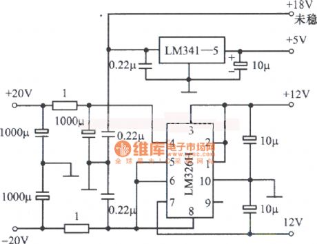
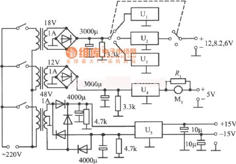
Multiple regulated power supply circuit composed of LM341-5 and LM326H
Published:2011/5/10 1:09:00 Author:Rebekka | Keyword: Multiple regulated power supply circuit
View full Circuit Diagram | Comments | Reading(851)
Dual-symmetric regulated power supply circuit composed of RC4194TK and RC4194D
Published:2011/5/10 1:10:00 Author:Rebekka | Keyword: Dual-symmetric regulated power supply
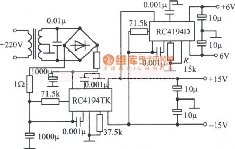
Dual-symmetric regulated power supply circuit composed of RC4194TK and RC4194D. (View)
View full Circuit Diagram | Comments | Reading(1182)
Multiple regulated power supply circuit composed of LM340 series
Published:2011/5/10 1:10:00 Author:Rebekka | Keyword: Multiple regulated power supply circuit
View full Circuit Diagram | Comments | Reading(734)
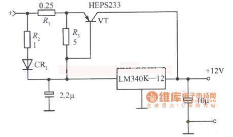
12V 10A regulated power supply circuit composed of LM340K-12
Published:2011/6/23 4:26:00 Author:Rebekka | Keyword: regulated power supply
View full Circuit Diagram | Comments | Reading(2711)
The Numerical Control DC Regulated Power Supply Circuit 6
Published:2011/7/22 21:55:00 Author:Michel | Keyword: Numerical Control, DC Regulated Power Supply
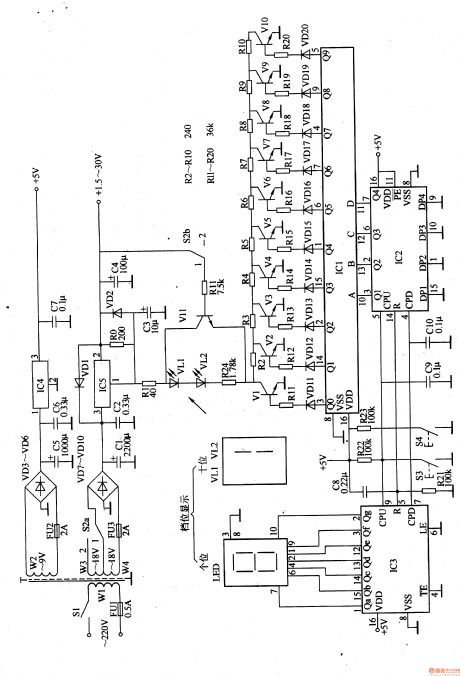
The control DC regulated power supply circuit introduced in the example uses light touch buttons and digital integrated circuit to control the output low voltage of voltage regulation circuit.Its output voltage range is 1.5-30V.The circuit uses 20 reversible gears stepping control(stepping value is 1.5V).The low voltage gear is 1.5-15V(zero to ninth gear) and high voltage gear is 16.5-30V(tenth to ninth gear) and the output votage gear is indicated by LED digital display.
Circuit's Work PrincipleThis control DC regulated power supply circuit is composed of voltage regulation circuit,control circuit and gear indication circuit and it is showed as the picture 5-25.
Voltage regulation circuit consists of mains switch,S1,gear selector switch,S2a ,FU1-FU3,mains transformer,T, rectifier diode ,VD10,capacitor,C1-C7,voltage regulator IC,IC4 and resistor,RO. (View)
View full Circuit Diagram | Comments | Reading(965)
| Pages:2/14 1234567891011121314 |
Circuit Categories
power supply circuit
Amplifier Circuit
Basic Circuit
LED and Light Circuit
Sensor Circuit
Signal Processing
Electrical Equipment Circuit
Control Circuit
Remote Control Circuit
A/D-D/A Converter Circuit
Audio Circuit
Measuring and Test Circuit
Communication Circuit
Computer-Related Circuit
555 Circuit
Automotive Circuit
Repairing Circuit