About SeekIC | Services | Payment | Advertisements service | Contact Us | Links
© 2008-2012 SeekIC.com Corp.All Rights Reserved.
Published:2011/8/25 20:49:00 Author:TaoXi | Keyword: Infrared, remote control, fan speed, control switch | From:SeekIC
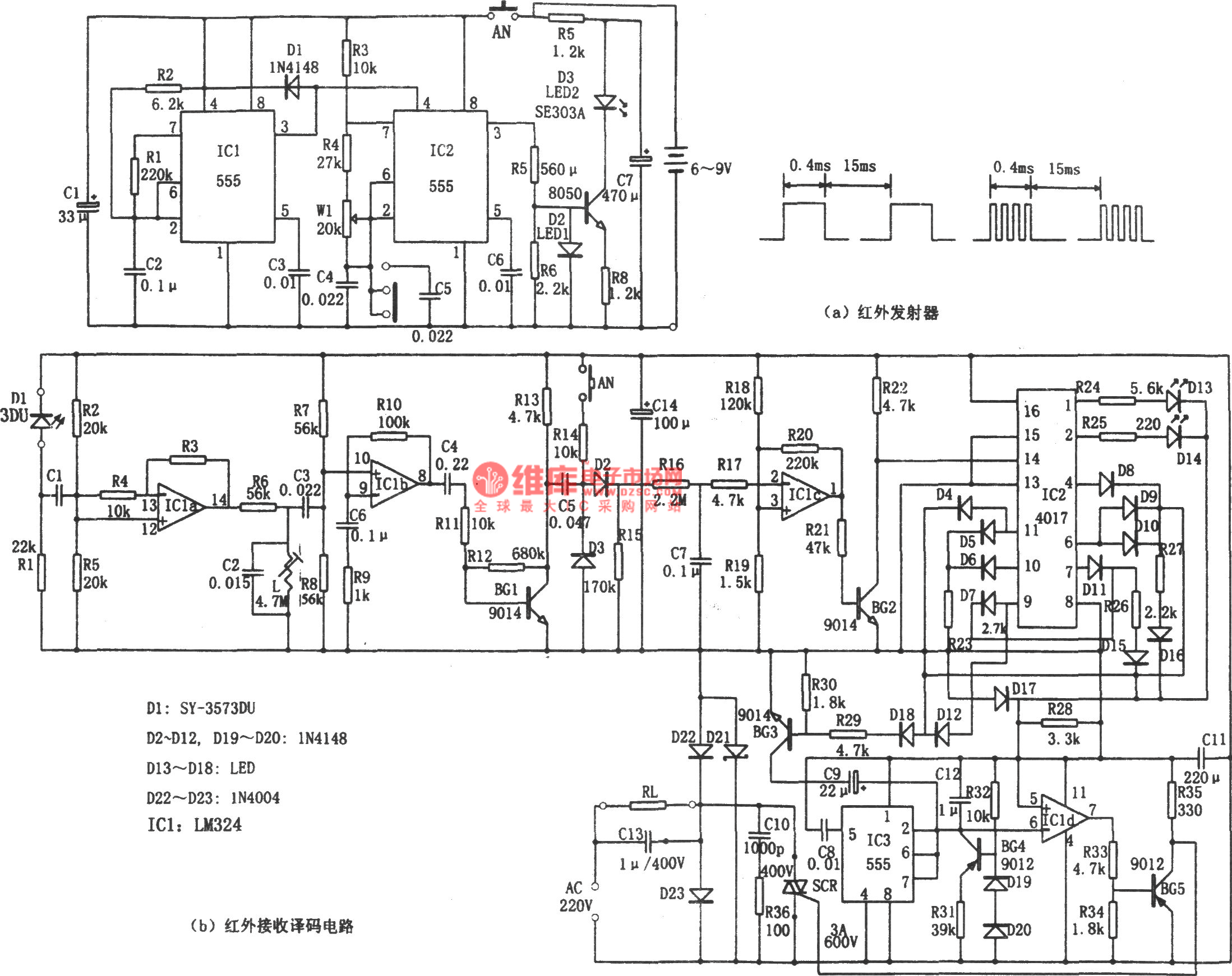
The infrared remote control fan speed control switch is as shown in the figure. This circuit is composed of the infrared transmitter, the infrared receiver, the decoder. The infrared transmitter includes the low-frequency multivibrator which is composed of the IC1 and D1, R1, R2, C2 and the multivibrator which is composed of the IC2 and R3, R4, C4, C5, W1. The oscillation cycle of IC1 is T=tcharging + tdischarging, the tcharging=0.693R2C2, it is about 400μs; tdischarging=0.693R1C2, it is about 15ms, the output waveform duty cycle is about 3%. IC2 is corresponding to two kinds of oscillation frequencies: f1=1.44/(R3+2R4+2Rw1)(C4),f2=1.44/(R3+2R4+2Rw1)(C4+C5), in the figure, the f=20kHz, f2=10kHz.
Reprinted Url Of This Article:
http://www.seekic.com/circuit_diagram/Remote_Control_Circuit/Infrared_remote_control_fan_speed_control_switch_555_LM324_CD4017.html
Print this Page | Comments | Reading(3)

Response in 12 hours
© 2008-2012 SeekIC.com Corp.All Rights Reserved.
Code: